
Related Manuals for Ferroli HXW LT


Summary of Contents for Ferroli HXW LT
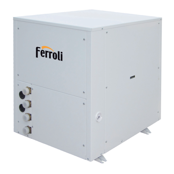
- Page 1 HXW LT WATER - WATER AND BRINE - WATER HEAT PUMPS FOR OUTDOOR OR INDOOR INSTALLATION INSTALLATION AND OPERATION MANUAL...
- Page 2 Dear Customer, Thank you for having purchased a FERROLI product. It is the result of many years of experiences and of particular research studies and has been made with top quality materials and advanced technologies. The CE mark guarantees that the products satisfy all the applicable European Directives.
-
Page 3: Table Of Contents
TABLE OF CONTENTS GENERAL FEATURES . . . . . . . . . . . . . . . . . . . . . . . . . . . . . . . . . . . . . . . . . . . . . . . . . . . . . . . . . . . . . . . . . . . . . . . . . . . . . . . . . . .4 General instructions . -
Page 4: General Features
Maximum absorbed current Refrigerant type and charge weight Unit weight Sound pressure level at 1 metre IP protection level Maximum pressure - high pressure side Maximum pressure - low pressure side PED certification body Ferroli Spa Via Ritonda 78/A (VR) Italy... -
Page 5: Unit Description
Unit identification code The codes that identify the units and the meaning of the letters used are described below. HXW LT IH 12 .1 VB AB 0 M 1 Power supply Unit type... -
Page 6: Description Of Components
GENERAL FEATURES Description of components External structure . Basement, lateral panels and upper panel, SAE 5/16” - UNF 1/2” - 20 equipped with pin, gasket and blind are thermally and acoustically insulated in order to minimize nut, as required for the use of R410A refrigerant (they allow thermal losses and noise emissions in the surroundings. -
Page 7: Control System
GENERAL FEATURES Control system The microprocessor controller is able to manage not only the unit itself but also all that components of the plant which allow to realize a complete system. The main functions of the control system are : - room temperature control according to the outdoor temperatu- 18:28 re (climatic control) -
Page 8: Options
GENERAL FEATURES Options Plant side Allows the circulation of the water on the plant side. Pump flow rate With the modulating pump is possible to control the flow rate in order to keep (standard, high head or modulating) management constant the temperature difference between inlet and outlet. Soft starter Reduces the compressor start current. -
Page 9: Accessories
GENERAL FEATURES Accessories Allow to reduce the transmission to the unit support plane of the mechanical vibrations generated by the compressor Rubber vibration dampers and by the pumps in their normal operating mode. to increase the thermal inertia of the plant and to guarantee a higher stability of the water sent Allows Plant tank to the hydronic distribution circuits. -
Page 10: Technical Data And Performances
GENERAL FEATURES Technical data Frame 12 .1 14 .1 17 .1 20 .1 23 .1 27 .1 Model U.M. 230 - 1 - 50 230 - 1 - 50 230 - 1 - 50 Power supply 400 - 3N - 50 400 - 3N - 50 400 - 3N - 50 V-ph-Hz... -
Page 11: Nominal Performances - High Temperature Plants
TECHNICAL DATA AND PERFORMANCES NOMINAL performances - HIGH TEMPERATURE plants Frame 12 .1 14 .1 17 .1 20 .1 23 .1 27 .1 Model U.M. 230 - 1 - 50 230 - 1 - 50 230 - 1 - 50 Power supply 400 - 3N - 50 400 - 3N - 50... -
Page 12: Nominal Performances - Standard Plants
TECHNICAL DATA AND PERFORMANCES NOMINAL performances - STANDARD plants Frame 12 .1 14 .1 17 .1 20 .1 23 .1 27 .1 Model U.M. 230 - 1 - 50 230 - 1 - 50 230 - 1 - 50 Power supply 400 - 3N - 50 400 - 3N - 50 400 - 3N - 50... -
Page 13: Nominal Performances - Radiant Plants
TECHNICAL DATA AND PERFORMANCES NOMINAL performances - RADIANT plants Frame 12 .1 14 .1 17 .1 20 .1 23 .1 27 .1 Model U.M. 230 - 1 - 50 230 - 1 - 50 230 - 1 - 50 Power supply 400 - 3N - 50 400 - 3N - 50 400 - 3N - 50... -
Page 14: Heating Performances
TECHNICAL DATA AND PERFORMANCES HEATING performances Heating capacity ( brine ) Heating capacity (water ) Inlet temperature - source side [°C] Inlet temperature - source side [°C] Power input ( brine and water ) The graphs allow to get the corrective factors to be applied to the nominal performances in order to obtain the real performances in the selected operating conditions. -
Page 15: Cooling Performances
TECHNICAL DATA AND PERFORMANCES COOLING performances Cooling capacity ( brine and water ) The graphs allow to get the corrective factors to be applied to the nominal performances in order to obtain the real performances in the selected operating conditions. The reference nominal conditions are : WATER-WATER units : W30W7 source : water in 30°C out 35°C... -
Page 16: Plant Side Hydraulic Performances
TECHNICAL DATA AND PERFORMANCES Plant side hydraulic performances Pressure drops - unit without options 27.1 23.1 20.1 17.1 14.1 12.1 1000 2000 3000 4000 5000 6000 7000 8000 Flow rate [ l/h ] Available static head - unit with option “Plant side flow rate management” : “Standard pump” 12.1 14.1 17.1... - Page 17 TECHNICAL DATA AND PERFORMANCES Available static head - unit with option “Plant side flow rate management” : “High head pump” 12.1 14.1 17.1 20.1 23.1 27.1 1000 2000 3000 4000 5000 6000 7000 8000 Flow rate [ l/h ] Available static head - unit with option “Plant side flow rate management” : "Modulating pump" 12.1 14.1 17.1...
-
Page 18: Source Side Hydraulic Performances
TECHNICAL DATA AND PERFORMANCES Source side hydraulic performances Pressure drops - unit without options 27.1 23.1 20.1 17.1 14.1 12.1 1000 2000 3000 4000 5000 6000 7000 8000 Flow rate [ l/h ]... -
Page 19: Operating Limits
TECHNICAL DATA AND PERFORMANCES Operating limits The graphs reported below show the operating area inside which the correct working of the unit is guaranteed. The dotted lines show the operating area when brine solutions in the source side hydraulic circuit are used. HEATING Inlet temperature - source side [°C] COOLING... -
Page 20: Electrical Data
TECHNICAL DATA AND PERFORMANCES Electrical data Frame 12 .1 14 .1 17 .1 20 .1 23 .1 27 .1 Model U.M. Unit Power supply 230-1-50 230-1-50 230-1-50 V-ph-Hz F.L.A. Maximum total current input 16,3 20,9 23,7 F.L.I. Maximum total power input Maximum total start current M.I.C. -
Page 21: Weights
TECHNICAL DATA AND PERFORMANCES Weights Frame 12 .1 14 .1 17 .1 20 .1 23 .1 27 .1 Model U.M. Components weights Unit without options Standard pump Plant side flow rate High head pump management Modulating pump Accessories Plant tank Transport weights Unit without options Standard pump... -
Page 22: Overall Dimensions
TECHNICAL DATA AND PERFORMANCES Overall dimensions Source return 1” M Unit with accessory "Plant tank" Source flow 1” M Plant return 1” M Plant flow 1” M Minimum operating area Rispect the free area around the unit as shown in figure in order to guarantee a good accessibility and facilitate maintenance and control operations. -
Page 23: Connections
CONNECTIONS Hydraulic connections To design properly the hydraulic system respect the local safety Expansion vessels setting regulations in force. All the units are equipped with expansion vessels on the plant It is always necessary to guarantee an appropriate water flow side. -
Page 24: Electrical Connections
CONNECTIONS Electrical connections The electrical wirings must be carried out by qualified personnel Upstream protection according to the regulations in force at the installation time in the An automatic switch suitable for ensuring protection against country of installation. Before starting any work on the electrical overcurrents and indirect contacts must be installed upstream circuit make sure that the unit power supply line is disconnected each power supply line. -
Page 25: Receiving And Positioning
RECEIVING AND POSITIONING Receiving Check on receiving The unit is supplied on a pallet suitable for the transport. It is As soon as the unit is received verify accurately the correspon- advisable to place protective material between the truck and the dance of the load to what was ordered to make sure that all unit to avoid damages to the unit. -
Page 26: Start Up
START UP Start up The following operations must be carried out only by properly trained personnel. To make the contractual warranty effective, start up must be carried out by authorized service centres. Before calling the service centre it is advisable to make sure that all the installation steps have been completed (positioning, electrical connections, hydraulic connections...). -
Page 27: Control System
CONTROL SYSTEM Control system configuration The control system can be configured in different ways in order to adapt itself to the user needs and to the kind of plant managed Outdoor User air sensor interface by the heat pump. The simpler configuration consists of unit controller (A) and outdoor air temperature sensor (B). -
Page 28: Heating And Cooling Circuits
CONTROL SYSTEM Heating and cooling circuits The controller of the heat pump is able to manage up to two zones : zone 1 : heating and cooling zone 2 : only heating The management of further zones, possibile by means of additional zone controllers, is not treated in this manual. For each zone can be set : set point daily or weekly operating time table... -
Page 29: Control System Devices Installation
CONTROL SYSTEM Control system devices installation REMOTE THERMOSTAT AND REMOTE CONTROL ( WIRED OR WIRELESS ) They should be located in the main room of the zone they manage taking into account the following criteria : the place of installation should be chosen so that the sensor can min. - Page 30 CONTROL SYSTEM OUTDOOR AIR SENSOR The device must be installed outside the building. The sensor is con- nected to the controller of the unit or to the wireless adaptor through a two wire cable ( the wires are interchangeable ). Ø...
-
Page 31: Wireless Devices Connection
CONTROL SYSTEM Wireless devices connection The wireless devices should be located in such a way that the In order to fulfill the connection two stages are necessary. transmission is as interference free as possible. The following Connection establishment : wireless devices are connected to criteria must be observed : the controller of the heat pump. -
Page 32: Control System Using
CONTROL SYSTEM Control system use The remote control (wired or wireless) allows the complete con- Also the remote thermostat contains a temperature sensor to trol of the system permitting to visualize and modify all the ope- measure the room temperature but allows the access to a limited rating parameters of the unit and is equipped with a temperatu- number of functions. - Page 33 CONTROL SYSTEM USER INTERFACE AND REMOTE CONTROL DISPLAY Heating : Comfort set point Heating : Reduced set point Heating : Frost Protection set point Cooling : Comfort set point Wait Xxxxxxxxxxxxxxxxxxxxxxxxxxx Change batteries Xxxxxxxxxxxxxxxxxxxxxxxxxxx Holiday function active Xxxxxxxxxxxxxxxxxxxxxxxxxxx Reference to heating circuit REMOTE THERMOSTAT DISPLAY Alarm message Maintenance messages...
- Page 34 CONTROL SYSTEM DHW button Allows to select the domestic hot water heating mode (indicated by a bar under the corresponding symbol). Domestic hot water heating mode ON domestic hot water temperature controlled according to the set time table protective functions active Domestic hot water heating mode OFF protective functions active Domestic hot water heating mode FORCED...
-
Page 35: Control System Programming
CONTROL SYSTEM Control system programming The settings that can not be modified directly through the buttons of the user interface and of the remote controls are accessible through the programming parameters, grouped inside the various programming menus. The menus concerning functions which are not active are automatically hidden. - Page 36 CONTROL SYSTEM Menu Level Parameter Function Preselection Phase 1 on Phase 1 off Phase 2 on Time table 5 Cooling circuit 1 Phase 2 off Phase 3 on Phase 3 off Default values Start Holidays program Heating circuit 1 Operating level Start Holidays program Heating circuit P...
-
Page 37: Remote Thermostat Programming
CONTROL SYSTEM Remote thermostat programming The configuration parameters of the remote thermo- Parameter Function stat must be set on the device itself. A long press (longer than 3 seconds) on the OC- Remote thermostat used as ru = 1 management heating circuit 1 CUPANCY button allows to enter the Programming ru = 3 management heating circuit 3... - Page 38 CONTROL SYSTEM Operating mode selection for heating and cooling circuits Heating circuit 1 : through the Heating button on the remote control Heating circuit P : through the Heating button on the remote thermostat Cooling circuit 1 : through the Cooling button on the remote control or through the parameter 901 Set point setting For each heating circuit 3 set points can be set : Comfort, Reduced and Frost Protecion.
-
Page 39: Inputs And Outputs
CONTROL SYSTEM Inputs and outputs The following table shows the list of the inputs and outputs available on the controller of the heat pump along with the expected use. Some inputs and outputs can be configured in a different way by the user in order to manage other plant components which are not contained inside the heat pump. -
Page 40: Alarms
CONTROL SYSTEM Alarms Alarms activation and reset no more shown on the display. Some of these alarms become The controller is able to perform a complete diagnosis of the unit manual reset alarms if the number of events in an hour exceeds detecting all the operating faults and notifying different alarms. - Page 41 CONTROL SYSTEM Code Alarm Reset Input Heat pump lock BSB address collision Wireless communication error on BSB bus Expansion module 1 Expansion module 2 Presence of 2 master clock time Clock without backup Communication error Maintenance message Source temperature too low High temperature compressor 1 outlet A / M High temperature compressor 2 outlet...
- Page 42 CONTROL SYSTEM Code Alarm Reset Input Heat pump lock Solar integration valve on plant buffer tank K8 missing Solar integration valve on swimming pool K18 missing Boiler pump Q10 missing Configuration error plant buffer tank Configuration error primary controller / system pump Configuration error pressureless header Sensor B10 missing Special sensor 2...
-
Page 43: Controller Technical Data
CONTROL SYSTEM Controller technical data Controller (with integrated expansion module) 230 Vac (+10% / -15%) Power supply 50 Hz / 60 Hz max 9,5 + 4,0 VA Safety class (EN 60730) Degree of protection (EN 60529) IP 00 Operating room temperature (not condensing) -20°C ... -
Page 44: Sensors Features
CONTROL SYSTEM Wireless transmitter on BSB bus 12 Vdc (G+ terminal of the controller) Power supply max 0,3 VA wired BSB bus Communication 2 wire connection not interchangeable (200m max) Safety class (EN 60730) Degree of protection (EN 60529) IP 20 Operating room temperature (not condensing) 0°C ... -
Page 45: Maintenance
MAINTENANCE Maintenance IMPORTANT BEFORE CARRYING OUT MAINTENANCE OR CLEANING OPERATIONS MAKE SURE THE UNIT POWER SUPPLY IS DISCON- NECTED. ANY ORDINARY OR EXTRAORDINARY MAINTENANCE OPERATION MUST BE CARRIED OUT BY SPECIALIZED AND AUTHORIZED PERSONNEL IN ORDER TO ENSURE COMPLIANCE WITH THE SAFETY REGULATIONS IN FORCE. N .B. -
Page 46: Safety And Pollution
SAFETY AND POLLUTION General considerations Accessing the unit The access to the unit must be granted exclusively to qualified personnel trained to operate on this type of units and provided with the necessary protection equipment. Moreover such personnel, to operate, must be authorized by the owner of the unit and recognized by the Manufacturer. - Page 47 SAFETY AND POLLUTION Respiratory tract protection For rescue and for maintenance works in tanks, use self-contained breathing apparatus. The vapours are heavier than air and can cause suffocation, reducing the oxygen available for breathing. Eye protection Total protection glasses. Hand protection Rubber gloves.
- Page 48 NOTE...
- Page 49 NOTE...
- Page 50 NOTE The manufacturer declines all responsibility for any inaccuracies in this manual due to printing or typing errors. The reserves the right to modify the products contents in this catalogue without previous notice.
- Page 51 NOTE...
- Page 52 Ferroli spa ¬ 37047 San Bonifacio (Verona) Italy ¬ Via Ritonda 78/A tel. +39.045.6139411 ¬ fax +39.045.6100933 ¬ www.ferroli.it...