
Related Manuals for CAME STYLO ME


Summary of Contents for CAME STYLO ME
- Page 1 EXTERNAL OPERATOR FOR SWING GATES 1 1 9DV 11E N Installation manual STYLO STYLO ME - STYLO RME English...
-
Page 2: Read Carefully
• This product should only be used for the purpose for which it was • Carefully section off the entire site to prevent unauthorised access, explicitly designed. Any other use is considered dangerous. CAME especially by minors and children • Be careful when handling ope- S.p.A. - Page 3 devices (i.e. transmitters) or any control devices away from children that must be indicated by proper pictograms and/or black and yellow as well, to prevent the operator from being activated accidentally • stripes • When using a selector or command in ‘hold-to-run’ mode, Frequently check the system, to see whether any anomalies or si- keep checking that there are no people in the area of operation of gns of wear and tear appear on the moving parts, on the component...
- Page 4 ☞ This symbol tells you what to say to end users. Description This product has been designed and built by CAME S.p.A. in compliance with applicable safety standards. The full range: 001STYLO-ME - 24 V DC non-reversible external gearmotor 001STYLO-RME - 24 V DC reversible external gearmotor...
- Page 5 Dimensions Technical data STYLO ME - STYLO RME (mm) Type Protection rating IP54 STYLO-BD Power supply 230 V AC (50/60 Hz) Motor power supply 24 DC (50/60 Hz) Current draw (max) Power 48 W Maximum torque 100 Nm Opening time (90°)
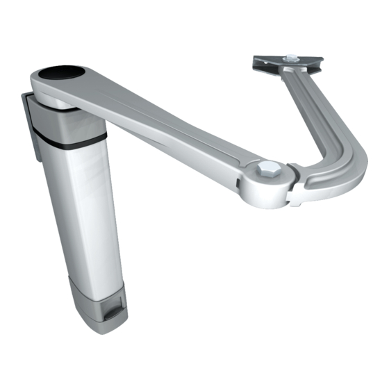
- Page 6 Main components STYLO-BS 1. Main body of the gearmotor 2. Upper cap 3. Lower cap 4. Hinged arm 5. STYLO-BS arm mounting bracket 6. Gearmotor mounting bracket 7. STYLO-BS cover 8. STYLO-BD cover 9. Slide guide 10. Opening stop 11. STYLO-BD slide rail 12.
-
Page 7: System Feasibility
System feasibility Installation must be carried out by qualified and experienced personnel in compliance with applicable regulations. Preliminary checks Before installing the operator: • Provide a suitable single-pole disconnection device, with a maximum of 3 mm between the contacts, to disconnect the power supply;... - Page 8 Types of cables and minimum thicknesses Type of Cable length Cable length Cable length Connection cable 1 < 10 m 10 < 20 m 20 < 30 m Control panel power supply 230V 3G x 1.5 mm² 3G x 2.5 mm² 3G x 4 mm²...
- Page 9 Example of a system 1. Gearmotor unit 2. Control panel 3. Radio receiver 4. Photocells 5. External key selector 6. Flashing light 7. Antenna 8. Transmitter 9. Mechanical stop N.B. For reversible versions, in- clude the blocking electro-lock. RG58 The data and information provided in this manual are subject to change at any time without prior notice.
- Page 10 Examples of applications = 300 mm max with 90° opening STYLO-BS Gate-leaf opening (°) A (mm) C (mm) D (mm) Gate-leaf opening (°) A (mm) C (mm) D (mm) STYLO-BD The data and information provided in this manual are subject to change at any time without prior notice.
-
Page 11: Installation
Installation The following illustrations are only examples, given that the space for securing the operator and accessories varies depending on the overall dimensions. The installation technician is responsible for choosing the most suitable solution. Preparation Set up corrugated tubes for the connections coming from the junction box. N.B. - Page 12 STYLO-BD 3 x M9 Trace all axes and dimensions, respecting the levels shown in the drawing , drill the marked points , then 4 x ø 8,5 secure the gearmotor mounting bracket to the wall or post and the slide ...
- Page 13 Drill the holes using an M8 male piece or use the M8 threaded inserts or suitable materials for securing the rail Note: the illustrations are mere examples, it is up to the install to choose the most suitable solution depending on gate leaf type and thickness.
- Page 14 Securing the gearmotor Remove the lower cap from the gearmotor. Secure the gearmotor to the fl ange using the four bolts supplied. Secure the upper cap. Ø 3,5 x 9,5 The data and information provided in this manual are subject to change at any time without prior notice.
- Page 15 Securing the transmission arm STYLO-BS UNI 5739 Ø 10x14 Assemble the hinged arm by joining the two half-arms with nuts and bolts. Lubricate the rotation pins Ø 10x39 Insert the hinged arm onto the gearmotor shaft and secure it using the screw and washer O-Ring 4100 Release the gearmotor, open the gate leaf and hook ...
- Page 16 STYLO-BD Assemble the slide guide to the transmission arm as shown in the drawing . Insert the guide into the rail Assemble the straight arm onto the gearmotor shaft . Cover the hole with the cap and secure it using the supplied screws Insert the end caps of the rail and the hole covers .
- Page 17 Release the gearmotor (see paragraph on manual release). Fully open the gate leaf and position the mechanical stop so that it coincides with the slide guide and then secure it . Fully close the gate leaf and position the closing mechanical stop so that it coincides with the slide guide ...
-
Page 18: Electrical Connections
Manual release of the non-reversible gearmotor Cut off mains power and open the protective trap door for release. Insert the key and turn it. Electrical connections Open the lower cap and make the necessary electrical connections. Complete installation by closing the lower cap again. The data and information provided in this manual are subject to change at any time without prior notice. - Page 19 Electrical connection of the STYLO ME gearmotor to the control panel 24 V (DC) gearmotor with 24 V (DC) gearmotor with delaying opening action delaying closing action ZL92 M1 N1 ENC1 EB1 M2 N2 ENC2 EB2 The data and information provided in this manual are subject to change at any time without prior notice.
- Page 20 Electrical connection of the STYLO RME gearmotor to the control panel 24 V (DC) gearmotor with 24 V (DC) gearmotor with delaying opening action delaying closing action ZL92 M1 N1 ENC1 EB1 M2 N2 ENC2 EB2 The data and information provided in this manual are subject to change at any time without prior notice.
-
Page 21: Troubleshooting
Troubleshooting MALFUNCTIONS POSSIBLE CAUSES CHECKS AND REMEDIES The gate does not open or close • No power supply • Check for power • The transmitter battery is flat • Replace the batteries • The transmitter is broken • Contact service •... - Page 22 Extraordinary maintenance The table below is used to note any extraordinary maintenance, repairs or improvements carried out by specialist companies. N.B.: Extraordinary maintenance must be carried out by specialist technicians Extraordinary maintenance log Installation technician Operator name stamp Date of intervention Technician signature Customer signature Intervention carried out _____________________________________________________________________...
-
Page 23: Dismantling And Disposal
CAME S.p.A. implements an EN ISO 14001 certified and compliant Environmental Management System at its plants, to ensure environmental protection. Please continue our efforts to protect the environment, something that CAME considers to be one of the foundations in developing its business and market strategies, simply by observing brief recommendations as regards disposal: DISPOSAL OF PACKAGING Packaging components (cardboard, plastic etc.) can be disposed of together with normal household waste without any difficulty, by... - Page 24 HU • A vállalatra, termékeire és a műszaki szervizre vonatkozó minden további információért az Ön nyelvén: HR • Za sve dodatne informacije o poduzeću, proizvodima i tehničkoj podršci: UK • Для отримання будь-якої іншої інформації про компанію, продукцію та технічну підтримку: www. came.com www. came.com CAME S.p.A.