Table of Contents
Advertisement
Quick Links
Advertisement
Table of Contents

Related Manuals for CAME STYLO Series


Summary of Contents for CAME STYLO Series
- Page 1 EXTERNAL AUTOMATION FOR SWING GATES INSTALLATION MANUAL STYLO-ME English...
- Page 2 Index Legend of symbols P. 4 Intended use and restrictions P. 4 Intended use P. 4 Restrictions P. 4 Description P. 4 Technical features P. 4 Dimensions P. 5 Description of parts P. 5 Installation P. 6 Preliminary checks P. 6 Examples P.
-
Page 3: Read Carefully
Warning Sings (e.g. gate plate). (i.e. that for which it was expressly built for). Any other use is Special instructions and to be considered dangerous. Came Cancelli Automatici S.p.A. advice for users is not liable for any damage resulting from improper, wrongful •... - Page 4 Restrictions Gate-leaf width (m) Gate-leaf weight (kg) Description This product is designed and built by CAME CANCELLI AUTOMATICI S.p.A. in compliance with current safety norms. Guaranteed 24 months unless tampered with. Technical features STYLO-ME Control board power supply: 230 AC 50/60Hz Motor power supply: 24V DC 50/60Hz Max draw.: 5A...
-
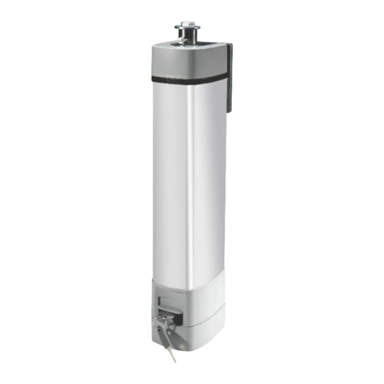
Page 5: Description Of Parts
Dimensions STYLO-ME STYLO-BD (mm) STYLO-BS 90° Description of parts 1) Main body of the gearmotor 2) Upper cap 3) Lower cap STYLO-BS 4) Hinged arm 5) STYLO-BS arm securing bracket 6) Gearmotor securing bracket 7) STYLO-BS cover 8) STYLO-BD cover 9) Slide guide 10) Opening stop 11) STYLO-BD slide rail... -
Page 6: Preliminary Checks
Installation Installation must be carried out by expert qualified personnel and in full compliance with current regulations. Preliminary checks Before installing, do the following: • Make sure you have suitable tubing and conduits for the electrical cables to pass through and be protected against mechanical damage;... - Page 7 STYLO-BD LARGHEZZA ANTA GATE LEAF WIDTH GATE LEAF WEIGHT PESO ANTA 0,80 1,20 1,80 40÷100 0÷150...
-
Page 8: Tools And Materials
Tools and materials Make sure you have all the tools and materials you will need for the installation at hand to work in total safety and compliance with the current standards and regulations. The figure shows some examples of installer’s tools. Cable list and minimum thickness Length of cable Length of cable... -
Page 9: Installing The Operator
Installing the operator The following illustrations are only examples, given that the space for securing the automation and accessories varies depending on the overall dimensions. Set up corrugated tubes for the connections coming from the junction box. N.B.: the number of tubes depends on the type of system installed and any accessories. Connection junction box. - Page 10 STYLO-BD 1b) position the gearmotor anchoring bracket and the slide rail following the measurements shown in the drawing. 3 x M9 4 x ø 8,5 ➊ ➊ ➋ ➌ Drill and thread the holes using an M8 male piece or use Ø 11 mm threaded inserts or any suitable materials for the rail to hold. Note: the illustrations are mere examples, it is up to the installer to choose the most suitable solution depending on gate-leaf type and thickness.
- Page 11 STYLO-BS Assemble the hinged-arm by joining the two half-arms with nuts and bolts. Lubricate the rotation pins. UNI 6593 Ø 6x18 UNI 5739 Ø 6x10 STYLO-BD Assemble the slide guide to the transmission arm as shown in the drawing. Insert the guide into the rail. 3) Remove the lower cap from the gearmotor.
- Page 12 a) insert the hinged-arm onto the gearmotor shaft and secure it using the washer and bolt; b) release the gearmotor, open the gate leaf and hook the arm using the nuts and bolts; c) Cover the hole using the cap. STYLO-BS UNI 5739 Ø...
- Page 13 Insert the end caps of the rail and the hole covers. Release the gearmotor (see paragraph on manual release) Fully open the gate leaf, position ➊ the mechanical stop so that it coincides with the slide guide and secure it. ➋...
-
Page 14: Manually Releasing The Gearmotor
- Open the lower cap and make the necessary electrical connections; - Close the lower cap again.. Manually releasing the gearmotor Cut off the main power and open the protective trap door for release; insert the key and turn it. -
Page 15: Electrical Connections
Electrical connections Electric connections to the ZL92 control panel 24 V (DC) gearmotor with 24 V (DC) gearmotor with delayed opening action delayed closing action M1 N1 ENC1 EB1 M2 N2 ENC2 EB2... -
Page 16: Important Safety Instructions
Safety instructions Important safety instructions This product must only be employed for its originally intended use. The automation installation using these gearmotors requires adequate safety systems on the gate leaves to detect any obstacles (e.g. sensitive edges), in compliance with EN12445 and EN12453 Technical Standards relative to the impact force generated by the moving gate. -
Page 17: Periodic Maintenance
Maintenance Periodic maintenance Periodic maintenance to be carried out by the end-user is as follows: wipe clean the glass surface of the photocells; check that the safety devices work properly; remove any obstructions. We suggest checking the state of lubrication and tightness of the anchoring screws on the operator. To check the efficiency of the safety devices, move an object in front of the photocells when gate is closing. -
Page 18: Extraordinary Maintenance
Periodic maintenance log for end-user (every 6 moths). Date Notes Signature Extra-ordinary maintenance The following table serves to note down any extraordinary maintenance, repairs or improvements performed by specialised firms. N.B.: Any extraordinary maintenance must be performed by specialised technicians. Extra-ordinary maintenance log Installer’s stamp Operator name... -
Page 19: Manufacturer's Declaration Of Conformity
CAME cancelli automatici s.p.a. employs a UNI EN ISO 14001 certified and compliant environmental protection system at its plants, to ensure that environmental safeguarding. We ask you to keep protecting the environment, as CAME deems it to be one of the fundamental points of its market operations strategies, by simply following these brief guidelines when disposing. - Page 20 (+34) 91 52 85 009 Jebel Ali Free Zone - Dubai Dubai (+34) 91 46 85 442 (+971) 4 8860046 (+971) 4 8860048 CAME United Kingdom Ltd. CAME United Kingdom Ltd. GREAT BRITAIN RUSSIA CAME Rus CAME Rus Unit 3 Orchard Business Park...