Avaya BCM50 Hardware Installation Manual
Hide thumbs
Also See for BCM50:
- User manual (82 pages) ,
- Technical configuration manual (18 pages) ,
- Configuration manual (14 pages)
Table of Contents
Advertisement
Quick Links
Download this manual
See also:
User Manual
Advertisement
Table of Contents

Related Manuals for Avaya BCM50


Summary of Contents for Avaya BCM50
- Page 1 BCM Rls 6.0 BCM50 Hardware & Installation Task Based Guide...
- Page 2 Avaya does not guarantee that these links will work all the time and has no control over the availability of the linked pages.
- Page 3 Contact Avaya Support Avaya provides a telephone number for you to use to report problems or to ask questions about your product. The support telephone number is 1-800-242-2121 in the United States. For additional support telephone numbers, see the Avaya Web site: http://www.avaya.com/support...
-
Page 4: Table Of Contents
Wiring Field Card ................16 Planning the Installation ..............17 Environment Checklist ..................18 Installing the BCM50 Unit in an Equipment Rack ......19 Installing the BCM50 Wall Mount Bracket ........20 Installing a BCM50 Expansion Unit ..........23 Supported Media Bay Modules ................ 23 Media Bay Module Descriptions .............. - Page 5 Upgrading to BCM Rls 6.0 ..........72 BCM50 Upgrade Flow Charts ............73 Upgrading from BCM50 Rls 1.0 to Rls. 6.0 ............. 73 Upgrading from BCM50 Rls 2.0 to Rls. 6.0 ............. 74 Upgrading from BCM50 Rls 3.0/5.0 to Rls. 6.0 ..........75 Pre-Upgrade Activities ..............
- Page 6 BCM50 Hardware & Installation Post-Upgrade Activities ..............86 Avaya Documentation Links .......... 87 NN40011-002 Issue 1.2 BCM50 Rls 6.0...
-
Page 7: Bcm50 Hardware & Installation
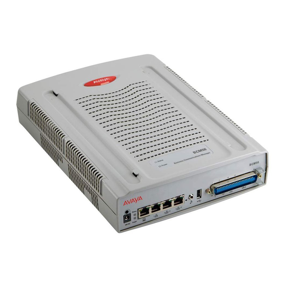
The BCM50 Main Unit provides telephony and simple data networking functions. It also provides connections for telephones, lines, and connection to a LAN. Choose the BCM50 if the network already has a router or if you do not require a router. -
Page 8: Bcm50B
BCM50 faceplate MOH). Music source port: A jack used to connect a music source to the BCM50 Main Unit. If you use this port, the music source connections on the amphenol are disabled. 1 x USB connection: USB Port is used for the Startup Profile, Loading... -
Page 9: Bcm50E
1x RJ45 LAN Port to connect the BCM to the customers LAN 2 x Expansion Ports: The expansion ports can provide connections to the internal ethernet switch within the BCM50 Main Unit. If the BCM50 system does not have BCM50 Expansion Units connected to these ports, you can use them to connect additional devices to the LAN ... -
Page 10: Bcm50Be
BCM50 faceplate MOH). Music source port: A jack used to connect a music source to the BCM50 Main Unit. If you use this port, the music source connections on the amphenol are disabled. 1 x USB connection: USB Port is used for the Startup Profile, Loading... -
Page 11: Other Available Features
BCM50 Hardware & Installation Other Available Features BCM50 supports the complete range of IP telephony features and other applications enabled through keycodes without the need for additional hardware: VoIP Gateway (H.323): Up to 12 VoIP trunks SIP trunks ... -
Page 12: Bcm50 Additional Components
BCM50 Expansion Unit This unit is designed to accommodate a media bay module (MBM). The BCM50 Main Unit supports up to two BCM50 Expansion Units. There are a maximum of 2 Expansion Units allowed Each Expansion Unit can support 1 Media Bay Module... -
Page 13: Flow Chart
BCM50 Hardware & Installation Flow Chart The flow chart below describes the BCM50 installation process. Where is the BCM50 being installed? Wall mount Rack Desk mount Install wall mount Install the BCM50 in a Apply the supplied bracket: refer to the rack: refer to the rubber feet. -
Page 14: Wall Mount Bracket
BCM50 Hardware & Installation Wall Mount Bracket If the BCM50 needs to be mounted on the wall, the wall mounting bracket is required. Each Expansion unit will require it’s own bracket. The wall mount bracket includes a cable management tray. -
Page 15: Rack Mount Shelf
BCM50 Hardware & Installation Rack Mount Shelf A shelf designed for mounting up to four BCM50 units into a standard 19 inch equipment rack. Requires a 19‖ rack mount shelf BCM50 clips into tabs on rack mount shelf ... -
Page 16: Wiring Field Card
Wiring Field Card An optional wiring field card (WFC) is available with the wall mount bracket, which provides RJ-45 connectors for all BCM50 Main Unit trunk and telephones. The wiring field card installs into the cable management tray of the wall mount bracket and connects to the telephony connector through a 50-pin header. -
Page 17: Planning The Installation
BCM50 Hardware & Installation Planning the Installation Before you install the BCM50 Main Unit or BCM50 Expansion Unit, it is good practice to follow a preparation check as follows. Preparation checklist: Number of lines / handsets / ATA2’s etc ... -
Page 18: Environment Checklist
Note: The installation area must be of sufficient height from the floor to prevent water damage. You also need the following equipment to install a BCM50 unit: mounting hardware (either a rackmount shelf, a wallmount bracket per unit or four rubber feet per unit) ... -
Page 19: Installing The Bcm50 Unit In An Equipment Rack
3. Fasten the rack mount shelf to the rack using the four rack screws 4. Place the BCM50 unit on the rack so that the unit’s feet are in the depressions in the shelf. 5. Move the unit forward until the unit’s feet touch the front side of the depressions. -
Page 20: Installing The Bcm50 Wall Mount Bracket
BCM50 system, remove the alignment tabs on the right side of the wall mount bracket. If this is the last unit on BCM50 system with multiple units, remove the alignment tabs on the left side of the wall mount bracket. - Page 21 15. Repeat these steps for each additional unit. 16. Insert the power supply retention clip into the BCM50 unit. 17. Slide the wall mount lock fully to the right (unlock position). NN40011-002 Issue 1.2 BCM50 Rls 6.0...
- Page 22 BCM50 Hardware & Installation 18. Align the feet on the BCM50 unit with the four holes in the wall mount bracket 19. Press the unit against the wall mount bracket and slide the unit down until it clicks in place.
-
Page 23: Installing A Bcm50 Expansion Unit
BCM50 Hardware & Installation Installing a BCM50 Expansion Unit Adding a BCM50 Expansion Unit increases the capacity of the BCM50 system by providing a method of adding a media bay module (MBM). Each MBM you add increases the number of trunks or extensions that you can connect to the BCM50 system. -
Page 24: Media Bay Module Descriptions
BCM system through four RJ-11 jacks on the front faceplate of the MBM. These jacks are labelled Line 1,Auxiliary, Line 2, Line 3, and Line 4. The auxiliary jack connects to Line 1. NN40011-002 Issue 1.2 BCM50 Rls 6.0... - Page 25 If the line is active, the auxiliary port line is disabled. When an analog telephone is connected to the auxiliary port, it can be used as an emergency telephone because this line remains active during a power outage. NN40011-002 Issue 1.2 BCM50 Rls 6.0...
- Page 26 (PSTN) lines. The GATM supports both pulse and tone dialing, as well as caller ID and disconnect supervision in selected markets throughout the world. The GATM uses an RJ-21 connector as the trunk interface. NN40011-002 Issue 1.2 BCM50 Rls 6.0...
- Page 27 Enhanced ringing capability — ASM8+ and GASM8 provide a ringing voltage of 2 REN/65 V rms per port. Calling line identification (CLID) The GASM8 is designated as an ONS (on-premise station) port. NN40011-002 Issue 1.2 BCM50 Rls 6.0...
- Page 28 8 analog lines (version dependant). It will utilise two DS30 buses one for the lines the other for the extensions. For example, if dipswitches are set to use bus 4 the analog trunks will use bus 4 and the DSM16 element will use bus 5. NN40011-002 Issue 1.2 BCM50 Rls 6.0...
-
Page 29: Media Bay Module Dipswitches
Lines), and G4/8x16 modules. The settings below refer to the switches on the right hand side of the GASM Media Bay Module. For the dip switches on the left side, set all the switches to on. GASM right hand side dipswitch settings (switch 1-3) NN40011-002 Issue 1.2 BCM50 Rls 6.0... -
Page 30: Installing A Media Bay Module Into The Expansion Unit
Country Profile dip switches Installing a Media Bay Module into the Expansion Unit 1. Ensure that you use an anti-static strap for the installation. 2. Expansion Units are not supplied with blanking plates NN40011-002 Issue 1.2 BCM50 Rls 6.0... -
Page 31: Expansion Unit Connections
4. For MBM removal, pull the ejector lever away from the unit The BCM50 Expansion Unit can be mounted in a rack, on a wall, or on a desktop. Typically, the BCM50 Expansion Unit is mounted in the same way... - Page 32 Plug the other end of the expansion cable into one of the expansion ports on the BCM50 Main Unit The LAN port on the BCM50 Expansion Unit is connected to the internal ethernet switch on the BCM50 Main Unit. You can use the BCM50...
-
Page 33: Bus Assignment
Onboard Digital/Analog Sets Internal Trunks/Sets via MBM’s External Sets (only enabled when using External DSM32(+) or (G)4/8x16 on bus 5) Trunks/Sets via MBM’s External Sets (only enabled when using External DSM32(+) or (G)4/8x16 on bus 7) NN40011-002 Issue 1.2 BCM50 Rls 6.0... -
Page 34: Bus Assignment & Default Line Numbers
Line Numbering Plan Line Type Line Number VoIP Trunks 001 - 012 Internal Analogue Physical Trunks 061-064 Or BRI Trunks (BCM 50 b/be models) External Physical Trunks 065 - 124 Target Lines 125 - 268 NN40011-002 Issue 1.2 BCM50 Rls 6.0... -
Page 35: Bus Assignment & Default Dn Numbers
285 - 300 External (G)4/8 x 16 Combo 801 - 816 285 - 300 Note: Buses 6 & 8 only appear if assigning a DSM32+ or (G)4/8 x 16 combo to buses 5 & 7. NN40011-002 Issue 1.2 BCM50 Rls 6.0... -
Page 36: Wiring Charts
Wiring Charts Main Unit Amphenol Wiring Ideally, extensions should be wired to a patch strip. The BCM50 Patch Panel allows direct connection to the amphenol cable via a 50-pin header. This BCM50 Patch Panel is designed for connection to the Main Unit. If standard... -
Page 37: Asm8(+)/Gasm/Dsm(+) Media Bay Module Amphenol Wiring
Slate-Red Black-Blue Ring Blue-Black Black-Orange Ring Orange-Black Black-Green Ring Green-Black Black-Brown Ring Brown-Black Black-Slate Ring Slate-Black Yellow-Blue Ring Blue-Yellow 17 - 25 No Connection Note: The ASM8/8+ and GASM MBM’s support 8 analog stations. NN40011-002 Issue 1.2 BCM50 Rls 6.0... -
Page 38: Adid4/8 Media Bay Module Amphenol Wiring
Port 2 Default Line Numbers Line Numbers ADID4 & ADID8 White-Blue Ring Blue-White White-Orange Ring Orange-White White-Green Ring Green-White White-Brown Ring Brown-White ADID8 Only White-Slate Ring Slate-White Red-Blue Ring Blue-Red Red-Orange Ring Orange-Red Red-Green Ring Green-Red NN40011-002 Issue 1.2 BCM50 Rls 6.0... -
Page 39: Gatm4/8 Media Bay Module Amphenol Wiring
Black-Green Ring Green-Black Black-Brown Ring Brown-Black 15 - 24 No Connection Can be used to connect a power Violet-Slate fail analog set. If system power Ring Slate-Violet fails the set will use line 1. NN40011-002 Issue 1.2 BCM50 Rls 6.0... -
Page 40: G4/8X16 Media Bay Module Amphenol Wiring
Module Ampenol Wiring section of this guide, consulting the DSM32 High column(s). 4x16 Media Bay Module Wiring The 4x16 MBM has RJ-11 ports for connecting Analog Trunks, and an amphenol connection for connecting the Digital Stations. The RJ-11 pin outs are as below. NN40011-002 Issue 1.2 BCM50 Rls 6.0... -
Page 41: Bri Ports
Module Ampenol Wiring section of this guide, consulting the DSM32 High column(s). BRI Ports The below BRI Port Wiring chart relates to the onboard BRI ports on BCM50b/be models, and also to the BRI Media Bay Modules. NN40011-002 Issue 1.2 BCM50 Rls 6.0... -
Page 42: Dtm Ports
Default Line Numbers Default Line Numbers 065-066 095-096 067-068 097-098 069-070 099-100 071-072 101-102 DTM Ports The digital trunks are connected to the DTM via the RJ-48C jack. The pin outs are detailed below. NN40011-002 Issue 1.2 BCM50 Rls 6.0... -
Page 43: Bcm50 Power Supply
BCM50 Power Supply The BCM50 power supply is an external device that connects to the BCM50 units. You must have one power supply for each unit you have in your BCM50 system An uninterruptible power supply (UPS) is an optional device that you connect to your BCM50 system. -
Page 44: Power Up Procedure
8. Plug the UPS power cord into the ac power source (wall outlet). Power Up Procedure The BCM50 takes approximately four to five minutes to boot up. There is no on/off switch on the system. 1. Plug the power supply cord into the BCM50 unit, with the power supply cable plugged into the wall outlet. - Page 45 Flashing Red Start-up Profile failure. Once the BCM50 has booted up and the BCM power and status lights are solid green, the system start up process can then be commenced. Please refer to the BCM50 System Start Up Guide for further details.
-
Page 46: Additional Information
You should also prepare the BCM for the maintenance procedure to take place. 1. Check for a recent backup of the BCM50 programming. If there is no recent backup, use Element Manager to back up all of the system data. - Page 47 BCM50 Hardware & Installation 5. Remove the 3 screws labelled ―A‖ on the base of the unit. 6. Position the main unit flat work area, top facing upwards. 7. Slide off the top of the main unit. NN40011-002 Issue 1.2 BCM50 Rls 6.0...
- Page 48 8. Gently disconnect the power cable, the SATA hard drive cable, and the fan connector cable. Power Cable SATA Cable & Connector Fan connector and Fan 9. Remove the two screws that hold the hard disk bracket to the chassis. NN40011-002 Issue 1.2 BCM50 Rls 6.0...
- Page 49 10. There are two connection clips (one either side of the chassis) that hold the hard drive bracket securely in position. These need to be gently prized inwards away from the outer chassis to allow the bracket to be lifted out. SATA cable Hard Drive connection clip NN40011-002 Issue 1.2 BCM50 Rls 6.0...
- Page 50 BCM50 Hardware & Installation 11. Lift the hard disk and hard disk bracket out of the main unit and place them on a flat, clean, static-free surface. Fan Cable SATA Cable Power cable NN40011-002 Issue 1.2 BCM50 Rls 6.0...
- Page 51 Route the power cable under the bracket and loop the hard disk cable. 17. Press down lightly on the top of the hard disk to ensure that the hard disk bracket is seated properly. NN40011-002 Issue 1.2 BCM50 Rls 6.0...
-
Page 52: Preparing The Multi-Image Hard Drive
The Multi-Image Hard Drive field Replaceable Unit contains multiple BCM software images. This allows for a common hard drive FRU to be installed in either a BCM50 or BCM450 chassis, and offers a range of software releases to be applied to the BCM having the hard drive replaced. - Page 53 Open up a SSH client such as PuTTY, and connect to the default OAM port address 10.10.11.1 3. Login to the BCM using the default details: User = nnadmin Password = PlsChgMe! NN40011-002 Issue 1.2 BCM50 Rls 6.0...
- Page 54 4. The Quick Configuration menu will display. Select 1 -> Install and Activate a BCM SW Release. 5. Detection of the BCM hardware type - i.e. BCM50 or BCM450 (BCM 200/400 5.0 or later systems will be detected as BCM450) – will begin.
- Page 55 (this will return you to the main menu). Otherwise, enter y to confirm and continue. Note: If the wrong software release is selected and confirmed, a new replacement hard drive will be required as the following process is irreversible. NN40011-002 Issue 1.2 BCM50 Rls 6.0...
-
Page 56: Replacing The Fan
You should also prepare the BCM for the maintenance procedure to take place. 1. Check for a recent backup of the BCM50 programming. If there is no recent backup, use Element Manager to back up of all the system data. - Page 57 11. Ensure the label faces the back of the unit. 12. Insert fan power cable. Replace the hard drive/bracket into original location. 14. Attach case and insert case screws. 15. Insert cables and power up. NN40011-002 Issue 1.2 BCM50 Rls 6.0...
-
Page 58: Replacing The Bcm 50(B)E Router Card
You should also prepare the BCM for the maintenance procedure to take place. 1. Check for a recent backup of the BCM50 programming. If there is no recent backup, use Element Manager to back up of all the system data. - Page 59 BCM50 Hardware & Installation 6. Remove the top part of the case. Router Card NN40011-002 Issue 1.2 BCM50 Rls 6.0...
- Page 60 15. Gently press down on the back of the router card to seat the router card in the connector on the Compact Service Card. 16. Re-attach case and cables and power up the BCM. NN40011-002 Issue 1.2 BCM50 Rls 6.0...
-
Page 61: Replacing The Cover Of The Main Unit
5. Turn the main unit over so you can access the screws holes on the bottom of the unit. 6. Insert the three case screws in the back of the unit and tighten them. NN40011-002 Issue 1.2 BCM50 Rls 6.0... -
Page 62: Installing The Wiring Field Card (Wfc)
BCM50 Hardware & Installation Installing the Wiring Field Card (WFC) You install the optional wiring field card (WFC) in the cable management tray of the BCM50 wall mount bracket. To install the WFC: 1. Clear the WFC installation area of all cables. -
Page 63: Connecting Cables To The Wiring Field Card
12. Connect the remaining wires (digital telephones, analog telephones, and analog trunks) to the WFC. 13. The 8-pin modular jacks on the WFC accept RJ45 or RJ11 modular plugs. 14. Connect cables to the BCM50 as required. NN40011-002 Issue 1.2 BCM50 Rls 6.0... -
Page 64: Connecting Cables To The Patch Panel
3. The cable locks in place. 4. Connect the wires (digital telephones, analog telephones, and analog trunks) to the patch panel. 5. Connect cables to the BCM50 as required. Reset Button The BCM Reset button performs two functions: 1. Initialises a graceful reboot 2. -
Page 65: Immediate Reboot
4 - Default Gateway. The default gateway for the system. 5 - DHCP Client Mode. Enable or disable the DHCP client. 6 - Commit Changes. Save changes to the IP settings. 7 - Reload Settings. Reload the existing IP settings. NN40011-002 Issue 1.2 BCM50 Rls 6.0... -
Page 66: Maintenance Cli
Use the following procedure to install PuTTY and connect to the BCM CLI. 1. Open Internet Explorer.In the address field type (replacing the relevant part with your BCM IP address): http://<bcm ip address>/ 2. Click on Go, or press Return on your keyboard. NN40011-002 Issue 1.2 BCM50 Rls 6.0... - Page 67 Element Navigation Panel to do this. 3. If you are presented with the Certificate Error window, click on Continue to this website (not recommended). 4. Accept any further security messages that you may get presented with. NN40011-002 Issue 1.2 BCM50 Rls 6.0...
- Page 68 PlsChgMe! Click on OK. 6. In the Welcome to BCM window, ensure the Main tab has been selected, and the BCM button clicked. 7. From the Applications list, select Other Administrator Applications and click Run. NN40011-002 Issue 1.2 BCM50 Rls 6.0...
- Page 69 9. The Administrator Applications screen will be displayed. 10. In the Administrator Applications window, click on the SSH Client (PuTTY) link, followed by Download PuTTY SSH Client. 11. Click on the Run button to install the application. NN40011-002 Issue 1.2 BCM50 Rls 6.0...
- Page 70 BCM50 Hardware & Installation 12. Click on Run again. 13. When installed, the PuTTY program will automatically launch. Enter the IP Address of the BCM in the Host Name (or IP Address) field, and click Open. NN40011-002 Issue 1.2 BCM50 Rls 6.0...
- Page 71 Then type in the password, again followed by Enter. 15. You will then be presented with the CLI. Make your selections as described in the Configuration CLI or Maintenance CLI sections of this guide. NN40011-002 Issue 1.2 BCM50 Rls 6.0...
-
Page 72: Upgrading To Bcm Rls 6.0
BCM50 Hardware & Installation Upgrading to BCM Rls 6.0 Any previous version of the BCM50 can be upgraded to BCM Rls 6.0. However, BCM50 Rls 1.0 systems should first be upgraded to BCM Rls 3.0 before performing the 6.0 upgrade. Upgrading directly from BCM Rls 2.0, 3.0 and 5.0 to BCM Rls 6.0 is supported. -
Page 73: Bcm50 Upgrade Flow Charts
Please read and follow the below processes to ensure that the correct steps are performed for your particular upgrade. Upgrading from BCM50 Rls 1.0 to Rls. 6.0 Create a Backup of the Rls 1.0 software: refer to the Backup &... -
Page 74: Upgrading From Bcm50 Rls 2.0 To Rls. 6.0
BCM50 Hardware & Installation Upgrading from BCM50 Rls 2.0 to Rls. 6.0 Create a Backup of the Rls 2.0 software: refer to the Backup & Restore Guide. Obtain a Keycode file with the Rls 6.0 upgrade entitlement, and also the Rls 6.0 Upgrade File and Factory Image: refer to the Pre- Upgrade Activities section of this guide. -
Page 75: Upgrading From Bcm50 Rls 3.0/5.0 To Rls. 6.0
Ensure the Time Zone is not set to Factory Default: refer to the Checking the Time Zone is Set Correctly section of this guide. Is the BCM50’s CSC hardware version 1? Refer to the Checking the BCM50 Hardware Version section of this guide. -
Page 76: Pre-Upgrade Activities
A http or https server Note: It is not recommended to perform the upgrade via the USB port, as the BCM50 USB port uses USB 1.1, i.e. the USB 1.1 data transfer rate would extend the time of the upgrade process. -
Page 77: Checking The Time Zone Is Set Correctly
BCM50 Upgrade Flow Charts section of this guide. The specific steps relating to CSC hardware version 1 models involve ensuring the BCM50 Rls 3.0 or 5.0 Factory Image is applied before upgrading to BCM50 Rls 6.0. Checking the Time Zone is Set Correctly Before any upgrade is performed, you should check that the Time Zone has been changed from the initial default setting, to the Time Zone of your locality. -
Page 78: Checking The Dhcp Server Setting
BCM Rls 6.0. Therefore, you should check that the DHCP setting is set to one of the following, to ensure that when the BCM50 is upgraded to BCM Rls 6.0, the appropriate DHCP service for the network is provided by the BCM50. -
Page 79: Applying The Keycode File
Note: This does not apply to the DHCP configured on the router card of the BCM50(b)e or BCM50(b)a models. If the DHCP service is enabled on the router card of these models, it should not be affected by the upgrade. - Page 80 BCM50 Hardware & Installation 1. In the Element Manager Configuration tab, open the System folder, and click on Keycodes. 2. Click on the Load File button. NN40011-002 Issue 1.2 BCM50 Rls 6.0...
-
Page 81: Performing The Upgrade
BCM50 Hardware & Installation 3. Browse to the location of the file and select it. 4. Click Open. 5. The new keycode file will be applied to the BCM50, allowing the software upgrade to be performed. Performing the Upgrade You may receive your upgrade files on DVD or in zip format. If your files are in zip format, ensure they are extracted to an accessible location before proceeding with the upgrade. - Page 82 Use the following procedure to apply the upgrade files to the BCM. 1. In the Element Manager Administration tab, open the Software Management folder and select Software Updates. 2. Click on the Get New Updates button to specify where the upgrade files are stored. NN40011-002 Issue 1.2 BCM50 Rls 6.0...
- Page 83 Click OK when the details have been entered. 5. For the My Computer option (i.e. the upgrade files are stored on your PC/laptop from which you’re performing the upgrade), click on the Browse button. NN40011-002 Issue 1.2 BCM50 Rls 6.0...
- Page 84 (you do not need to select any specific or individual files) and click on Select. 7. Click on the appropriate upgrade, and click on Apply. 8. Click Yes in the Confirm window. NN40011-002 Issue 1.2 BCM50 Rls 6.0...
-
Page 85: Applying The Factory Image
Note: Do not apply the Factory Image unless you are sure the upgraded system is functioning correctly. You will not be able to perform a Software Reset and restore a previous backup if the Factory Image is applied before checking system functionality. NN40011-002 Issue 1.2 BCM50 Rls 6.0... - Page 86 BCM50 Hardware & Installation Post-Upgrade Activities Below is an overview of activities once the BCM50 has been upgraded to BCM Rls 6.0, and the Factory Image has been applied: Apply any new patches, e.g. from the Smart Update DVD.
- Page 87 BCM50 Hardware & Installation Avaya Documentation Links Installation – System Upgrade Guide NN40011-002 Issue 1.2 BCM50 Rls 6.0...
- Page 88 BCM50 Hardware & Installation NN40011-002 Issue 1.2 BCM50 Rls 6.0...