
Related Manuals for Delta UPS102N2002N0B0


Summary of Contents for Delta UPS102N2002N0B0
- Page 1 The power behind competitiveness Delta UPS - Amplon Family N Series, Single Phase 1/ 2/ 3 kVA User Manual www.deltapowersolutions.com...
- Page 2 Failure to heed these instructions and warnings will void the warranty. Copyright © 2015 by Delta Electronics Inc. All Rights Reserved. All rights of this User Manual (“Manual”), including but not limited to the contents, information, and figures are solely owned and reserved by Delta Electronics Inc.
-
Page 3: Table Of Contents
Table of Contents Table of Contents Chapter 1 : Important Safety Instructions --------------------------- 1 Safety Instructions ---------------------------------------------- 1 Storage ------------------------------------------------------------- 4 Chapter 2 : Introduction --------------------------------------------------- 5 General Overview ----------------------------------------------- 5 Exterior & Dimensions ----------------------------------------- 5 Package List ------------------------------------------------------ 6 Chapter 3 : Operation Panel ---------------------------------------------- 8 LED Indicators --------------------------------------------------- 8 Multi-function Buttons ------------------------------------------ 9... - Page 4 Chapter 9 : Troubleshooting --------------------------------------------27 Chapter 10 : Maintenance ------------------------------------------------30 10.1 UPS ----------------------------------------------------------------30 10.2 Batteries ----------------------------------------------------------30 10.3 Fan -----------------------------------------------------------------31 Appendix 1 : Technical Specifications-------------------------------32 Appendix 2 : Warranty ----------------------------------------------------34 Amplon N Series...
-
Page 5: Chapter 1 : Important Safety Instructions
Chapter 1 Important Safety Instructions Chapter 1 : Important Safety Instructions 1.1 Safety Instructions Installation Warnings Before installation and usage, please read this User Manual thoroughly. This helps you to use the product correctly and safely. Install the UPS in a well-ventilated area, away from excess moisture, heat, dust, flammable gas or explosives. - Page 6 Usage Warnings This is a class-A product. In a domestic environment, this product may cause ra- dio interference, in which case, the user is required to take adequate measures. The UPS can be used to power computers and associated peripheral devices, such as monitors, modems, cartridge tape drives, external hard drives, etc.
- Page 7 2. The UPS cannot connect any external battery pack. 1. There are six sealed lead-acid built-in batteries. UPS302N2000N0B0 3kVA 72Vdc 2. The UPS cannot connect any external battery pack. UPS102N2002N0B0 1kVA 24Vdc 1. There is no built-in battery. Long Backup UPS202N2002N0B0 2kVA 48Vdc 2.
-
Page 8: Storage
3. Wear rubber gloves and boots. 4. Do not lay tools or metal parts on the top of batteries. 5. Before battery removal, replacement or installation, disconnect any circuit connected to the batteries. Do not connect the batteries in reverse; otherwise, a risk of electric shock or fire accidents might occur. -
Page 9: Chapter 2 : Introduction
Chapter 2 Introduction Chapter 2 : Introduction 2.1 General Overview The N series UPS is a single-phase on-line UPS providing reliable and consistent sine-wave quality power to your electronic equipment. It adopts the latest technol- ogy and the highest quality components providing output power factor up to 0.9 and its efficiency in on-line mode can reach at maximum 93%. -
Page 10: Package List
2.3 Package List NOTE : 1. If there is any damage or anything missing, please immediately contact the dealer from whom you purchased the unit. 2. If the UPS needs to be returned, carefully repack the UPS and all of the accessories using the original packing material that came with the unit. -
Page 11: Chapter 2 Introduction
Chapter 2 Introduction Long Backup Model: UPS102N2002N0B0 (1kVA)/ UPS202N2002N0B0 (2kVA) / UPS302N2002N0B0 (3kVA): SETUP Item Q’ty 1/ 2kVA 3kVA 1 PC User Manual 1 PC Terminal Copper * 3 PCS Cable Tie (Type A) * 1 PC Cable Tie (Type B) *... -
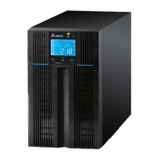
Page 12: Chapter 3 : Operation Panel
Chapter 3 : Operation Panel 3.1 LED Indicators RUN TIME 3.3 LCD Display (inclduing SET TEST BATT LOAD 3.4 7-Segment Display) °C 3.2 Multi-function Buttons SETUP 3.1 LED Indicators Description Indicates the output status. 1. ON (green): There is output 2. -
Page 13: Multi-Function Buttons
Chapter 3 Operation Panel 3.2 Multi-function Buttons Multi- function Description Button The button has multi-function. Please refer to the following for de- tailed information. 1. Turn-on: In standby/ bypass mode, press and hold the button for 3 sec- onds, release it after you hear one beep and the UPS will run in on-line mode. - Page 14 Multi- function Description Button The button has multi-function. Please refer to the following for de- tailed information. 1. Turn-off: In on-line mode, press and hold the button for 3 seconds, release it after you hear one beep and the inverter will be off and the UPS will transfer to run in standby/ bypass mode.
-
Page 15: Lcd Display
Chapter 3 Operation Panel 3.3 LCD Display RUN TIME SET TEST BATT LOAD °C Icon Naming Description AC Icon Indicates the input source status. 1. ON: The AC input is within the acceptable bypass range. 2. Flashing: The AC input is out of the accep- table bypass range but is still sufficient to let the unit operate in on-line mode. - Page 16 Icon Naming Description Battery Illuminates when the UPS is operating in battery Mode Graph mode. Bypass Illuminates when the UPS is operating in bypass Mode Graph mode. Buzzer Icon Illuminates when the buzzer is disabled. Warning Icon 1. ON: The unit is shut down due to an internal fault or an environmental fault.
- Page 17 Chapter 3 Operation Panel Icon Naming Description Load Level Indicates the status of load level. Bar Graph 1. ON: The bar graph illuminates according to the load level * 2. Flashing: The bar graph flashes when there is an overload situation. Battery Level Indicates the status of battery level.
-
Page 18: 7-Segment Display
3.4 7-Segment Display Column A RUN TIME SET TEST BATT LOAD °C 7-Segment Display Column B NOTE : You might need to read the word shown in Column A together with that in Cloumn B to understand the display meaning. Icon Description 1. - Page 19 Chapter 3 Operation Panel Icon Description When the word ‘SET’ illuminates, it means that the UPS is in the setup mode. You can set up the following items via the LCD. For how to setup, please refer to 5.5 Setup Mode. 1.
-
Page 20: Flow Chart Of The 7-Segment Display
Icon Description Means ‘voltage’. Means ‘percentage’. Means ‘frequency’. Means ‘kVA’. Means ‘kW’. Means ‘minute’. Means the UPS’s internal temperature. 3.5 Flow Chart of the 7-Segment Display The following flow chart helps you to understand how to go through each display screen. - Page 21 Chapter 3 Operation Panel Press the button for 0.1 second to view the next display. Press the button for 0.1 Press the button for 0.1 second to view the next display. second to view the next display. Press the button for 0.1 Press the button for 0.1 second to view the next display.
-
Page 22: Chapter 4 : Rear Panel
Chapter 4 : Rear Panel Standard Model: UPS102N2000N0B0 (1kVA)/ UPS202N2000N0B0 (2kVA)/ UPS302N2000N0B0 (3kVA): M I N I S L O T M I N I S L O T M I N I S L O T OUTPUT SOCKET I N P U T B R E A K E R 250V AC. - Page 23 Chapter 4 Rear Panel Long Backup Model: UPS102N2002N0B0 (1kVA)/ UPS202N2002N0B0 (2kVA)/ UPS302N2002N0B0 (3kVA): M I N I S L O T M I N I S L O T M I N I S L O T OUTPUT SOCKET I N P U T B R E A K E R 250V AC.
-
Page 24: Chapter 5 : Operation Modes
Chapter 5 : Operation Modes NOTE : 1. Please refer to Chapter 3 : Operation Panel to learn how to operate the operation panel and understand the display meaning. 2. Each of the display diagrams shown in this chapter is for reference only. Actual display depends on the operation of the UPS. -
Page 25: Setup Mode
Chapter 5 Operation Modes 5.5 Setup Mode Press the scrolling button for more than 3 seconds and the LCD will go into the setup menu. Please note that only qualified service personnel can perform setup action. In setup mode, you can set up the following items: 1. - Page 26 NOTE : Please note that only qualified service personnel can perform setup action. Setup Mode Flow Chart Original Display T>3 seconds Inverter Voltage Setup T>3 seconds T>0.1S T=0.1S T>0.1S T>0.1S Inverter Frequency Setup T>3 seconds T>0.1S T=0.1S T>0.1S T>0.1S Bypass Range Setup T>3 seconds T>0.1S T=0.1S...
-
Page 27: Chapter 6 : Turn-On & Turn-Off Procedures
Chapter 6 Turn-on & Turn-off Procedures Chapter 6 : Turn-on & Turn-off Procedures NOTE : Please refer to Chapter 3 : Operation Panel to learn how to operate the operation panel and understand the display meaning. WARNING: Before performing turn-on procedures: 1. -
Page 28: Turn-Off Procedures
6.2 Turn-off Procedures NOTE : Before performing turn-off procedures, verify that all of the loads connected to the UPS have been safely shutdown. 1. In on-line mode, if you want to turn off the UPS, press and hold the button for 3 seconds and release it after you hear one beep. -
Page 29: Chapter 7 : Alarm
Chapter 7 Alarm Chapter 7 : Alarm Condition Alarm Battery Mode The audible alarm beeps once every 2.1 seconds. Low Battery The audible alarm beeps once every 0.6 second. Battery The audible alarm beeps once every 2.1 seconds. Missing/ Weak Battery/ Battery Replacement/ * Overload... -
Page 30: Chapter 8 : Optional Accessories
Chapter 8 : Optional Accessories Item Function Dust Filter Prevents dust from entering into the UPS to ensure UPS reliability and to prolong product life. Mini SNMP Card Monitors and controls the status of the UPS via a network system. Mini Relay I/O Card Increases the quantity of dry contacts. -
Page 31: Chapter 9 : Troubleshooting
1. When a problem occur, please check if the following situation exists before contacting Delta service personnel: Is the main input voltage present? 2. Please have the following information ready if you would like to contact the Delta service personnel: Unit information including model, serial number, etc. - Page 32 Error Possible Meaning Solution Code Cause Inverter The UPS has Contact service personnel. Fault abnormalities. DC-DC Fault The UPS has Contact service personnel. abnormalities. Abnormal The UPS has Contact service personnel. Output/ abnormalities. Inverter Voltage O/P Short Output has a short- 1.
- Page 33 Chapter 9 Troubleshooting B. About other problems that might happen: Problem Possible Cause Solution Overload The UPS is Decrease your connected overloaded. loads. Battery Missing Internal battery cables 1. Contact service are not connected or personnel. not firmly connected. 2. Connect the internal battery cables and connect them firmly.
-
Page 34: Chapter 10 : Maintenance
Chapter 10 : Maintenance 10.1 UPS UPS Cleaning Regularly clean the UPS, especially the slits and openings, to ensure that the air freely flows into the UPS to avoid overheating. If necessary, use an air-gun to clean the slits and openings to prevent any object from blocking or covering these areas. -
Page 35: Fan
Chapter 10 Maintenance 10.3 Fan Higher temperatures shorten fan life. When the UPS is running, please check if each fan works normally and make sure if the ventilation air can move freely around and through the UPS. If not, contact service personnel. NOTE : Please ask your local dealer or customer service for more maintenance information. -
Page 36: Appendix 1 : Technical Specifications
Appendix 1 : Technical Specifications Model N-1K N-2K N-3K Standard Model 1kVA/0.9KW 2kVA/1.8KW 3kVA/2.7KW Power Rating Long Backup Model 1kVA/0.8KW 2kVA/1.6KW 3kVA/2.4KW Waveform Pure Sine Wave Nominal Voltage 220/230/240 Vac 175 ~ 280 Vac (100% load); Voltage Range 80 ~ 175 Vac (50% ~ 100% load) Input Frequency 50/60 Hz ±... - Page 37 Appendix 1 Technical Specifications Model N-1K N-2K N-3K Backup Time Standard Model: Up to 7 Min. (Standard) Standard Model: 3hrs to 90% Recharge Time Long Backup Model: Depends on the capac- Battery ity of the connected external battery pack(s) Standard Model: 1A Long Backup Model: 4A Charge Current (can be increased to 8A via installation...
-
Page 38: Appendix 2 : Warranty
Appendix 2 : Warranty Seller warrants this product, if used in accordance with all applicable instructions, to be free from original defects in material and workmanship within the warranty period. If the product has any failure problem within the warranty period, Seller will repair or replace the product at its sole discretion according to the failure situation. - Page 40 5013231700...