Table of Contents
Advertisement
Advertisement
Table of Contents
Troubleshooting

Related Manuals for Windsor Chariot 2 iVac 24 AVT


Summary of Contents for Windsor Chariot 2 iVac 24 AVT
- Page 1 Operating instructions (ENG) MODELS: CV24 10125760 CVC24 10125770 All Machines between Serial Number (Ref No.3*) to Serial Number (Ref No.4*). *See Serial Number Page or Call Manufacturer Read these instructions before using the machine. 86374850 G 08/27/15...
-
Page 2: Machine Data Label / Overview
The unit also has an accessory wand and hose for cleaning small areas and non-floor surfaces. Warranty Registration Thank you for purchasing a Windsor product. Warranty registration is quick and easy. Your registration will allow us to serve you better over the lifetime of the product. -
Page 3: Table Of Contents
Table of Contents Parts Machine Data Label / Overview ....2 Bumper ....... . . 48 Table of Contents. -
Page 4: How To Use This Manual
How To Use This Manual This manual contains the following sections: The SAFETY section contains important information regarding hazardous or unsafe practices of the • How to Use This Manual machine. Levels of hazards are identified that could • Safety result in product damage, personal injury, or severe •... -
Page 5: Safety
Safety IMPORTANT SAFETY INSTRUCTIONS When using this machine, basic precaution must always be followed, including the following: READ ALL INSTRUCTIONS BEFORE USING THIS MACHINE. To reduce the risk of fire, electric shock, or injury: Use only indoors. Do not use outdoors or expose to rain. This appliance is for dry use only. Use only as described in this manual. - Page 6 Safety MESURES DE SÉCURITÉ IMPORTANTES Lors de l'utilisation d'un appareil à batteries, il est nécessaire de respecter systématiquement des mesures de sécurité de base, comme suit : NOTE DE TOUTES CES MESURES AVANT D'UTILISER CETTE MACHINE. Pour réduire les risques d'incendie, de chocs électriques, ou de blessures : N'utiliser cette machine qu'en intérieur.
-
Page 7: Hazard Intensity Level
WHEN SERVICING MACHINE: Avoid moving parts. Do not wear loose clothing; jackets, shirts, or sleeves when working on the machine. Use Windsor approved replacement parts. Batteries emit hydrogen gas. Explosion or fire can result. Keep sparks and open flame away. Keep battery compartment open during charging. - Page 8 Éviter les parties amovibles. Ne pas porter de vêtements amples, tels que des vestes, des chemises ou des vêtements avec manches lors de l'utilisation de la machine. Utiliser les pièces détachées Windsor homologuées. Les batteries émettent le gaz d'hydrogène. L'explosion ou le feu peut résulter. Étincelles de subsistance et flamme nue loin.
-
Page 9: Safety Label Locations
Safety Safety Label Locations These drawings indicate the location of safety labels on the machine. If at any time the labels become illegible, promptly replace them. EMPLACEMENT DE L'ÉTIQUETTE DE SÉCURITÉ REMARQUE : Ces dessins indiquent l'emplacement des étiquettes de sécurité sur la machine. Si, à tout moment, les étiquettes deviennent illisibles, contactez votre représentant autorisé... -
Page 10: Operations
Operations Technical Specifications ITEM DIMENSION/CAPACITY Nominal power 1224 W Rated Voltage 36 Volts DC Rated Amperage 34 amps Batteries 3 X12 Volt 130 AH @ 20 hr. rate Battery Compartment Dimensions 20-1/2 in. x 13 in. x 10 in. tall (330mm x 521mm x 254mm) Propelling Motor .21 HP (157 W) Cylindrical Brush Motor... - Page 11 Operations ITEM MEASURE Height 51.8 in (1316 mm) Length 44.0 in (1118 mm) Width without deck 24.5 in (622 mm) Width of deck 23.25 in (581 mm) Width with side broom 25.9 in (658 mm) WIDTH LENGTH HEIGHT This appliance is not intended for use by persons (including children) with reduced physical, sensory or mental capabilities, or lack of experience and knowledge, unless they have been given supervision or instruction concerning use of the appliance by a person responsible for their safety.
-
Page 12: How This Machine Works
Operations The function of the operator control system is to control How This Machine Works the direction and speed of the machine. The directional The Chariot® iVacuum 24 ATV™ is a battery powered, control system consists of the direction control switch, self-propelled, vacuum intended for commercial use. -
Page 13: Components
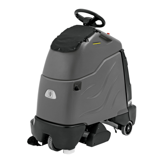
Operations Components 1. Accessory Hose 2. Brush Deck 3. Console 4. Control Panel 5. Main Cover 6. Pedal Platform 7. Rear Cover 8. Side Broom 9. Vacuum Bag 86374850 Chariot iVac 24... -
Page 14: Drive Controls
Operations Drive Controls 86374850 Chariot iVac 24... - Page 15 Operations 1. Key Switch 2. Emergency Stop/Brake Switch 3. Directional Control / Drive Reset Switch 4. Throttle Pedal 5. Horn Button 6. Steering Wheel 7. Speed Control 8. Battery Discharge Indicator Light 9. Hour Meter 10. Operator Presence Switch 1. KEY SWITCH Controls the power for machine functions.
- Page 16 Operations 4. THROTTLE PEDAL Controls the speed of the vehicle within the speed control setting selected. Pressing the pedal causes the machine to travel in the direction selected by the Directional Control Switch. To increase speed, increase pressure on the pedal. To decrease speed, decrease pressure on the pedal.
- Page 17 Operations 8. BATTERY DISCHARGE INDICATOR Indicates the charge level of the batteries. The indicator will be illuminated if the batteries have a sufficient charge. A slow, continous flash indicates the batteries require charging. The Battery Lockout function will activate when the batteries are low. Once active, the LED status indicator will begin to flash slowly and the controller will inhibit the side broom, main brushes, and vacuum operation.
-
Page 18: Vacuum Controls
Operations Vacuum Controls 1. Function Mode Switch The first two positions are for transport only. See drive controls section. A1 - Light vacuuming This mode is used for light vacuuming. In this mode the machine will propel at fast speed. The ‘floating’ brush deck is in the down position. -
Page 19: Pre-Run Machine Inspection
Operations Pre-run Machine Inspection Emergency Stop Procedures Do a pre-run inspection to find possible problems that 1. Release the throttle pedal by lifting right foot. could cause poor performance or lost time from break- 2. Turn machine power off with key switch by turning down. -
Page 20: Normal Vacuuming
Operations Normal Vacuuming To Begin Vacuuming Plan the vacuuming pattern in advance. The longest track is around the perimeter of the area to be cleaned. For efficient operation, the runs should be the longest When operating the machine around people, pay possible without turning or stopping. -
Page 21: To Stop Vacuuming
Operations 7. Tilt back panel to retrieve a new clean paper bag To Stop Vacuuming from the storage compartment in left side wall of 1. Remove foot from throttle pedal allowing pedal to main cover. return to neutral. 8. Return back panel to operating position. 2. -
Page 22: Maintenance
Maintenance Service Schedule BEFORE AFTER EACH MAINTENANCE EACH WORK WORK 50 HRS 100 HRS 200 HRS PERIOD PERIOD Check water level of batteries after charging; add distilled water if necessary Check that the vacuum box lid seal tightly Visually check for damaged or worn tires. Check vacuum hose connections. -
Page 23: Batteries
Maintenance Batteries 1. Cover Retainer Latch 2. Rear Cover 3. Battery Connector-Machine 4. Batteries 5. Battery Tray 86374850 Chariot iVac 24... - Page 24 Maintenance Batteries (Wet Cell) The batteries provide the power to operate the machine. The batteries require regular maintenance to keep them operating at peak efficiency. The machine batteries will hold their charge for long periods of time, but they can only be charged a certain number of times.
-
Page 25: Battery Maintenance
Maintenance Battery Maintenance 1. When cleaning the batteries, use a solution of baking soda and water. Do not allow the cleaning When servicing machine, avoid contact with fluid to enter the battery cells, electrolyte will be battery acid. neutralized. 2. Maintain the proper electrolyte level in each battery cell. -
Page 26: Checking Battery Specific Gravity
Maintenance Checking Battery Specific Gravity Use a hydrometer to check the battery specific gravity. CHECKING GRAVITY a. Hydrometer Battery b. Battery NOTE: Do not take readings immediately after adding distilled water, if the water and acid are not thoroughly mixed, the reading may not be accurate. Check the hydrometer readings against this chart. -
Page 27: Charging Batteries
Maintenance Use a 36 volt, 20 amp maximum output DC charger Charging Batteries which will automatically shut off when the batteries are fully charged. 1. Stop the machine in a clean, well ventilated area When servicing machine, avoid contact with next to the charger. -
Page 28: Changing Batteries
Maintenance 5. Replace the battery caps, and leave them in place 7. Disconnect main positive lead and secure cable while charging. terminals away from batteries. 6. Unplug the battery connector from the machine. 8. Loosen both terminals on each jumper cable and remove one at a time. -
Page 29: Delta Q Ic650 Charger Maintenance Instructions
Maintenance Delta Q IC650 Charger Maintenance Instructions 1. Do not expose charger to oil, dirt, mud or direct heavy water spray when cleaning the vehicle or machine. 2. The enclosure of the charger meets IP66, making it dust-tight and protected against powerful water jets. The AC inlet connection itself, when mated, is rated to IP20, which is not protected against water. -
Page 30: Delta Q Ic650 Charger Operating Instructions
Maintenance Delta Q IC650 Charger Operating Instructions - The charger may become hot during charging. Use hand protection to safely handle the charger during charging. - Extension cords must be a 3-wire cord no longer than 30m (100') at 10 AWG or 7.5m (25') at 16 AWG, per UL guidelines. -
Page 31: Selecting A Charge Profile
Maintenance *Process will time out and profile will remain Selecting a Charge Profile unchanged if there is 15 seconds of inactivity, a profile 1. Disconnect AC input from the charger, or from the number is allowed to display three times, or if AC power wall outlet. -
Page 32: Configuring The Ic650 Charger Using A Usb Flash Drive
Maintenance Configuring the IC650 Charger Using a USB Flash Drive Using the Delta Q software, USB storage drives can be pre-programmed to certain charger configuration. To use the USB port, follow these steps: 1. Insert the USB flash drive at any time, except during a charge cycle. Stop the charge cycle by removing AC power or the DC connection to the batteries. -
Page 33: Charge Tracking Data
Maintenance Charge Tracking Data All IC650 Chargers record data such as amp hours returned, charge cycle completion or interruption, and the charge profile being used. This data can be very useful in vehicle or machine diagnostics. To retrieve this data, follow these steps: 1. -
Page 34: Circuit Protection
Maintenance Circuit Protection Circuit Breakers 3 A Fuse Circuit breakers interrupt the flow of power in the event of an electrical overload. When a circuit breaker is tripped, reset it by pressing the exposed button. If a circuit breaker continues to trip, the cause of the electrical overload should be found and corrected. -
Page 35: Vacuum Diverter Valve Maintenance
Maintenance Vacuum Diverter Valve Maintenance For maintenance and removal of the vacuum diverter valve follow the steps below. 4. Remove the three (3) screws and washers 1. Remove hoses from diverter valve. retaining the diverter valve assembly to the console. 2. - Page 36 Maintenance Brush Deck 1. Debris Tray 2. Brush Deck Door 3. Side Broom 4. Deck Lift Actuator 86374850 Chariot iVac 24...
-
Page 37: Brush Removal
Maintenance Brush Deck Debris Tray Removal The dual cylindrical head is designed to agitate the 1. Release the debris tray spring clip. carpet while vacuuming. The first brush pushes debris 2. Slide the debris tray away from machine. backwards. The second brush, brushing forward picks up debris and throws it into the debris tray. -
Page 38: Remove Brush Deck
Maintenance Brush Motor Carbon Brush Replacement 1. Scribe alignment mark on motor barrel to motor cap. Remove two bolts. Do not use a pressure washer to clean around the brush motors. Use tap pressure only. 2. Remove end cap from motor. NOTE: Motors contain two wave washers in cap. - Page 39 Maintenance 8. Remove move three (3) screws that secure To Repair or Replace Vacuum Motor vacuum motor. Replace motor. 1. Remove four (4) screws from top of control panel. 2. Tip control panel back from console to expose vacuum motor wires. 3.
-
Page 40: Drive Motor
Maintenance Drive Motor Drive Chain Tension The drive chain should deflect about 1/4 inch on either Drive Motor Carbon Brush Replacement side of the loop when the opposite side is tight. To adjust chain tension: 1. Remove bumper. 2. Loosen five (5) screws that hold the drive gear Do not use a pressure washer to clean around the motor and slide the gear motor up until the chain brush motors. -
Page 41: Inclines
Maintenance Drive gear engaged Inclines Machine can be driven. When navigating an incline the machine may come to a stop. Turn the machine off. Wait 5 minutes and start the Rotate lever firmly in direction of arrow machine and proceed up the incline. Overheating may occur if you do not wait the full 5 minutes. -
Page 42: Machine Tie-Downs
Maintenance Preparation for Loading/Unloading Trailer Before loading or unloading machine from trailer, brush deck must be in the up position. When transporting the machine on a trailer or in a truck, in addition to using tie-downs, be sure to block the tires to prevent the machine from rolling. -
Page 43: Troubleshooting
Maintenance Troubleshooting PROBLEM CAUSE SOLUTION No machine function Console lid is open Close console lid No power to machine Battery disconnected Check all battery cable connections Emergency shut-off activated Reset Battery cables corroded Clean connections Faulty key switch Replace switch Batteries not plugged in Plug batteries in On Board charger plugged in... - Page 44 Maintenance Troubleshooting PROBLEM CAUSE SOLUTION Vacuum motor does not run, or Faulty vacuum circuit or switch Check wires & connections runs slowly Worn vacuum motor brushes Replace brushes, check commutator Vacuum circuit breaker tripped Reset circuit breaker Vacuum and brush do not turn on Circuit breaker tripped Reset Full bag or clog in system (bag full light Replace bag, empty debris tray, check...
-
Page 45: Battery Discharge Indicator Troubleshooting
Maintenance Battery Discharge Indicator Troubleshooting The battery indicator flashes when a problem occurs. The table below list solutions for the indicated problems. Number of Problem Solution flashes The battery needs charging, there is a bad connection to If the connections are good, try the battery or dependent on the programming, may charging the battery. - Page 46 Notes 86374850 Chariot iVac 24...
-
Page 47: Parts
Parts PARTS 86374850 Chariot iVac 24... -
Page 48: Bumper
Bumper 86374850 Chariot iVac 24... - Page 49 Bumper SERIAL NO. PART NO. QTY DESCRIPTION NOTES FROM 86345220 BUMPER, TRIM 86276980 SCREW 5/16-18 X 2 HHCS SS 86010670 WASHER 5/16 FLAT SS 86276070 SCR, 5/16-18 X 3/4 CARRIAGE SS 86270830 NUT 5/16-18 HEX NYLOCK SS 86323950 PAD, TIP 86327510 SCR, KA50X16, PT OHS, WN1412, A2 SS 86339800...
-
Page 50: Back Panel
Back Panel A TORQUE 50 IN/OZ 86374850 Chariot iVac 24... - Page 51 Back Panel SERIAL NO. PART NO. DESCRIPTION NOTES FROM 86345080 BRACKET, VAC BAG, LOWER 86345070 BRACKET, VAC BAG, UPPER 86344800 GASKET, VAC ENCLOSURE 48" 86341040 BAG, VAC-10 PACK 86340640 HOUSING, VAC BAG 86327910 SCR, KA50X25, PT OHS, WN1412, PLTD 86327590 LANYARD, 15.0 W/LOOP &...
-
Page 52: Brush Deck Debris Tray
Brush Deck Debris Tray NOTE : EXPOSED RAIL ORIENTATION 86374850 Chariot iVac 24... - Page 53 Brush Deck Debris Tray SERIAL NO. PART NO. QTY DESCRIPTION NOTES FROM 86014990 SCR, M5X20, SHCS, ISO4762, SS 86342400 GASKET, DEBRIS TRAY, END 86340290 MOUNT, DEBRIS TRAY, 20” 86408760 CLIP, DEBRIS TRAY SPRING 86173350 WASHER, M5, FL, ISO7089, SST 86024750 NUT, M5 HEX NYLOCK, SS 86327510 SCR, KA50X16, PT OHS, WN1412, A2 SS...
-
Page 54: Brush Deck Drive
Brush Deck Drive A TORQUE 18 IN/LBS 86374850 Chariot iVac 24... - Page 55 Brush Deck Drive SERIAL NO. PART NO. DESCRIPTION NOTES FROM 86343870 HOUSING ASM, BRUSH DRIVE 86343860 BELT, TWIN 5MM GT2, 15W, 130T 86343850 PULLEY, 32T 5MM GT, 15W 86343840 PULLEY, 18T 5MM GT, 15W 86343830 PULLEY ASM, 22T 5MM GT, 15W 86339570 COVER, DRIVE HOUSING 86224660...
-
Page 56: Brush Deck
Brush Deck A TORQUE 64 IN/LBS 86374850 Chariot iVac 24... - Page 57 Brush Deck SERIAL NO. PART NO. QTY DESCRIPTION NOTES FROM 86356810 ASM, DEBRIS TRAY, 20 86346070 COUPLER, 2 JAW, 35MM 86343160 SCR, M5X40, SHCS, ISO4762, SS 86343200 GASKET, 1/16THKX3/8WX19.50L 86343190 GASKET, 1/16THKX3/8WX2.17L 86343020 PLATE, COUNTERBALANCE 86173350 WASHER, M5, FLAT, ISO7089, SS 86340500 BRUSH, VACUUM 20 86348840...
-
Page 58: Brush Deck Lift
Brush Deck Lift A TORQUE 10 FT/LBS 86374850 Chariot iVac 24... - Page 59 Brush Deck Lift SERIAL NO. PART NO. QTY DESCRIPTION NOTES FROM 86270830 NUT 5/16-18 HEX NYLOCK SS 86010670 WASHER 5/16 FLAT SS 86259420 WASHER, THRUST .51ID X 1 ODBRO 86228990 BEARING,FLNGD,.314ID X.502OD 86340820 LIFTER, DECK 86340920 PLATE, LIFT LINKAGE 86340910 ARM, DECK LIFT 86277130 SP SCREW 5/16-18X1.00 CARRIAGE SS...
-
Page 60: Brush Deck & Lift Mounting
Brush Deck & Lift Mounting A TORQUE 10 FT/LBS 86374850 Chariot iVac 24... - Page 61 Brush Deck & Lift Mounting SERIAL NO. PART NO. QTY DESCRIPTION NOTES FROM 86277130 SCREW 5/16-18X1.00 CARRIAGE SS 86259420 WASHER, THRUST .51ID X 1 ODBRO 86010670 WASHER 5/16 FLAT SS 86270830 NUT 5/16-18 HEX NYLOCK SS 86228990 BEARING,FLNGD,.314ID X.502OD 86341310 BRKT, BRUSH DECK PIVOT 86276680 SCR, 1/4-20 X 1.5 HHMS SS...
-
Page 62: Brush Deck - Side Broom
Brush Deck - Side Broom A TORQUE 10 FT/LBS 86374850 Chariot iVac 24... - Page 63 Brush Deck - Side Broom SERIAL NO. PART NO. QTY DESCRIPTION NOTES FROM 86342160 BRUSH, 9.5 IN, NYLON, BLACK 86341960 PLATE, WEIGHT 86341070 BRACKET, SIDE BROOM MOUNT 86341060 BRACKET, SIDE BROOM PIVOT 86008650 COTTER, 1/4 RING 86328040 PIN, CLEVIS, 1/4 X 2.0 L 86322470 MOTOR, 36VDC, 90 DEG, 1/16 HP 86279140...
-
Page 64: Console
Console 86374850 Chariot iVac 24... - Page 65 Console SERIAL NO. PART NO. QTY DESCRIPTION NOTES FROM 86346600 SPACER, .320ODX.257IDX.505L NY 86005810 NUT 1/4-20 HEX NYLOCK SS 86346090 GASKET,.85X.85X.125 THICK 86346050 CONSOLE, TRIM 86349280 SCREW, 1/4-20 X 1 PHPNHMS SS BLK ZNPLT 86238460 HOOK, STRAP 86341700 BRACKET, SWITCH, NO BAG 86340740 PLATE, BAG INLET RETAINER 86010630...
-
Page 66: Console Mounting
Console Mounting 86374850 Chariot iVac 24... - Page 67 Console Mounting SERIAL NO. PART NO. QTY DESCRIPTION NOTES FROM 86326340 PIN, CLEVIS 5/16 X 4.0, PLTD 86228990 BEARING,FLNGD,.314ID X.502OD 86264940 CABLE TIE, 11.38" UL/CSA 86326320 BRACKET, HINGE UPPER 86327680 SWITCH, INTERLOCK 86270860 NUT, 10-24 U-TYPE SPEED 86277110 SCR, 10-24 X 3/4 PPHMS SS 86328860 NUT, 5/16 PUSH-LOCK, PLTD 86326330...
-
Page 68: Control Panel 1
Control Panel 1 86374850 Chariot iVac 24... - Page 69 Control Panel 1 SERIAL NO. PART NO. QTY DESCRIPTION NOTES FROM 86357790 PANEL, CONTROL, CS24 RE 86337210 SPACER, .14ID X .25OD X .38, NYL 86336110 RELAY, SPST-NO 86336100 CLIP, RELAY 86347250 PCBA, RELAY OMRON ll 86372280 CONTROLLER, CV24 RE 86326390 CONN, 8MM PITCH, 10 POSN 86005710 NUT, 1/4-20 HEX W/STAR...
-
Page 70: Control Panel 2
Control Panel 2 86374850 Chariot iVac 24... - Page 71 Control Panel 2 SERIAL NO. PART NO. QTY DESCRIPTION NOTES FROM 86332510 BOOT, SEAL PUSH BUTTON 11M 86001260 BOOT, CB 3/8-32 UNS 86348640 LED, BAG FULL INDICATOR 86348960 LED, BATTERY INDICATOR 53217380 HANDHOLD OPERATIONAL CONCEPT 86293930 BODY, SWITCH, BUTTON 86313950 SWITCH, SPDT 3 POSN MOM, ARROW 86292590 SWITCH, E-STOP...
-
Page 72: Decals
Decals 86374850 Chariot iVac 24... - Page 73 SERIAL NO. PART NO. QTY DESCRIPTION NOTES FROM 86344680 LABEL, RIGHT, iVAC 24 ATV 86344670 LABEL,LEFT, iVAC 24 ATV 86004970 LABEL WINDSOR LOGO DOMED 86358080 LABEL, CONTROL PANEL, CV24 86335710 LABEL, BATTERY WIRING 86334860 LABEL, HEPA FILTRATION 86374850 Chariot iVac 24...
-
Page 74: Drive Lower
Drive Lower NOTE: TERMINAL HARDWARE INSTALLED, 2 LOCATIONS A TORQUE 15/18 FT/LBS B TORQUE 120 IN/LBS C TORQUE 15 FT/LBS D TORQUE 60 IN/LBS E TORQUE 100 IN/OZ AFTER 86374850 Chariot iVac 24... - Page 75 Drive Lower SERIAL NO. PART NO. QTY DESCRIPTION NOTES FROM 86326710 KEY, 5 X 5 X 16 86321670 WASHER, WHEEL SPACER 86319810 AXLE, DRIVE WHEEL 86319670 SLEEVE, BEARING 86364010 MOTOR, TRACTION 86378440 KIT, BRUSHES, DRIVE MOTOR 98408960 BRAKE REPLACEMENT SMALL STAND ON 86342280 SPROCKET, DRIVE 11T 86342320...
-
Page 76: Drive Chain
Drive Chain A TORQUE 78 IN-LBS 86374850 Chariot iVac 24... - Page 77 Drive Chain SERIAL NO. PART NO. QTY DESCRIPTION NOTES FROM 86005710 NUT, 1/4-20 HEX W/STAR 86005810 NUT, 1/4-20 HEX NYLOCK SS 86006800 SCR, 10-32 X 1/2 PHTR PLT 86010630 WASHER, 1/4 X 5/8 FLAT SS 86010670 WASHER, 5/16 X 3/4 SS 86010780 WASHER, 1/4 SPLIT 86014440...
-
Page 78: Drive Mounting
Drive Mounting 11 10 86374850 Chariot iVac 24... - Page 79 Drive Mounting SERIAL NO. PART NO. QTY DESCRIPTION NOTES FROM 86344620 BRACKET, LINKAGE MOUNT 86319730 BRACKET, LINKAGE MOUNT, LEFT 86331630 BRACKET, ROLLER GUIDE 86010670 WASHER, 5/16 X 3/4 SS 86276690 SCR, 5/16-18 X 1.75 CARR SS 86276070 SCR, 5/16-18 X 3/4 CARRIAGE SS 86270830 NUT, 5/16-18 HEX NYLOCK SS 86344630...
-
Page 80: Frame & Rear Wheels
Frame & Rear Wheels BOTTOM OF FRAME 86374850 Chariot iVac 24... - Page 81 Frame & Rear Wheels SERIALNO. PART NO. QTY DESCRIPTION NOTES FROM 86326260 BRACKET, FRAME LEFT 86326250 BRACKET, FRAME RIGHT INCLUDES 86350170 ASM FRAME, CV24 ITEM 8 & 9 86326220 SPACER, FLG .887ID X 1.055D X .345LG 86318030 AXLE, 20MM X 562 MM 86369160 WHEEL, 6.00X1.58, GRY W/BEARINGS (2*)
-
Page 82: Main Cover
Main Cover .75" A TORQUE 100 IN-OZ 86374850 Chariot iVac 24... - Page 83 Main Cover SERIAL NO. PART NO. DESCRIPTION NOTES FROM 86002400 CLAMP, 2.00 WORM GEAR X .312 86346060 COVER, TRIM CV24 86346100 COVER, TRIM OBC CVC24 86345730 HOSE, Ø1.5", ACCESSORY 86345360 BRACKET, ROLLER 86345200 BRACKET, BRACE 86345120 BRACKET, HOSE SUPPORT 86346000 SPRING, EXT, 1.0 OD X 8.5L 86341570 BRACKET, SPRING MOUNT...
-
Page 84: On Board Charger
On Board Charger 86374850 Chariot iVac 24... - Page 85 On Board Charger SERIAL NO. PART NO. DESCRIPTION NOTES FROM 86345140 BRACKET, CHARGER 86340780 ROLLER, HOSE 86340950 SCR, 3/8 X 1.5, LAG, PLTD 86372000 CHARGER, DELTA Q, ASM, 36V (1*) 86276960 SCREW, 1/4-20 X 1 CARRIAGE SS 86273980 SCREW, 10-32 X .75 PHPNHMS SS 86259410 WASHER, THRUST .51 ID X1ODX.063 86228990...
-
Page 86: Pedal Platform
Pedal Platform 86374850 Chariot iVac 24... - Page 87 Pedal Platform SERIAL NO. PART NO. QTY DESCRIPTION NOTES FROM 86007110 SWITCH, 25A SPST 125-250V SNAP 86172980 SCR, KA50X10, PT OHS, WN1412, PLTD 86264930 CABLE TIE, 3.5" UL/CS 86326150 BRKT, LINEAR POT 86326140 PIN, DOWEL .25 X 2.75, STEEL 86318010 PEDAL, HEEL 86318000 PEDAL, ACCELERATOR...
-
Page 88: Pedal Platform Mounting
Pedal Platform Mounting 86374850 Chariot iVac 24... - Page 89 Pedal Platform Mounting SERIAL NO. PART NO. QTY DESCRIPTION NOTES FROM 86327510 SCR, KA50 X 16, WN1412 A2 SS 86198440 CLAMP, 1/4 PLASTIC CABLE 86327910 SCR, KA50X25, PT OHS, WN1412, PLTD 86173330 WASHER, M5, FLAT, ISO7093, SS 86374850 Chariot iVac 24...
-
Page 90: Steering
Steering 86374850 Chariot iVac 24... - Page 91 Steering SERIAL NO. PART NO. QTY DESCRIPTION NOTES FROM 86259610 WHEEL STEERING 40 SPLINE HUB 86271610 NUT 5/8-18 HEX NYLOCK THN 86279420 WASHER,.75IDX1.25ODX.125THK NY 86228790 BEARING FLANGE .88ODX.75IDX.75 86378370 ASM, SHAFT, STEERING, CHARIOT 2 86234810 COVER, STEERING WHEEL 86374850 Chariot iVac 24...
-
Page 92: Vacuum
Vacuum See maintenance section for motor mounting detail. 86374850 Chariot iVac 24... - Page 93 Vacuum SERIAL NO. PART NO. QTY DESCRIPTION NOTES FROM 86345290 FILTER, Ø6X9, HEPA/CARBON 86345280 FILTER, Ø6X9, SPUNBOND/CARBON 86345270 FILTER, Ø6X9, SPUNBOND 86345610 SCR, 3/8-16X1/2, THUMB ROSETTE 86340760 MOUNT, POST FILTER 86237440 GASKET, 4.06 X 2.50 X .38 86275890 SCR, 1/4-20 X 5/8 HHCS5 (PLTD) 86010630 WASHER 1/4 ID X 5/8 OD SS 86340710...
-
Page 94: Vacuum Diverter Valve
Vacuum Diverter Valve SEE MAINTENANCE SECTION FOR REMOVAL INSTRUCTIONS 11 12 A TORQUE 100 IN-OZ 86374850 Chariot iVac 24... - Page 95 Vacuum Diverter Valve SERIAL NO. PART NO. DESCRIPTION NOTES FROM 86345660 SOLENOID, 24VDC, 198 OZ FORCE 86344930 PLATE, FLAP LEVER 86344750 HOSE, Ø2.0 VAC X 25 86340750 PLATE, SOLENOID 86340700 LINK, SOLENOID 86370820 DIVERTER VALVE HOUSING ASM OPEN OPEN 86279450 WASHER, #6 X .40 FLAT 86279100 WASHER, #4 INT STAR...
-
Page 96: Vacuum Accessories
Vacuum Accessories 86374850 Chariot iVac 24... - Page 97 Vacuum Accessories SERIAL NO. PART NO. QTY DESCRIPTION NOTES FROM 86344870 BRUSH, DUST 69034030 NOZZLE, AKW 86000090 TUBE, 20” EXTENSION 86344700 COVER, CONSOLE 86349130 SCR, 10-32 X 3/4 PHOVALMS SS BLK ZINC 69069540 COMBINATION NOZLE DN32 OPTIONAL 86374850 Chariot iVac 24...
-
Page 98: Accessory Hose - Optional
Accessory Hose - Optional 86374850 Chariot iVac 24... - Page 99 Accessory Hose - Optional SERIAL NO. PART NO. QTY DESCRIPTION NOTES FROM 86349210 HOSE, ASM, 1 1/2, 20 ACCESSORY 86350200 BRACKET, HOSE SUPPORT 86006870 SCREW #10B X 1/2 PHSM BLK 98409580 KIT, 20' ACCESSORY HOSE COMPLETE 86374850 Chariot iVac 24...
-
Page 100: Wand Bracket - Optional
Wand Bracket - Optional 86374850 Chariot iVac 24... - Page 101 Wand Bracket - Optional SERIAL NO. PART NO. QTY DESCRIPTION NOTES FROM 86345300 BRACKET, WAND SUPPORT 86006870 SCREW, #10B X 1/2 PHSM BLK 98409570 KIT, WAND BRKT COMPLETE 86374850 Chariot iVac 24...
-
Page 102: Wiring Battery
Wiring Battery MAIN WIRING HARNESS 86374850 Chariot iVac 24... - Page 103 Wiring Battery SERIAL NO. PART NO. QTY DESCRIPTION NOTES FROM 86329720 BATT, CBL, ASM, JUMPER 86334280 CBL, 6GA 5/16" RING 15" NOT SHOWN 86329710 BATT,CBL,ASM,W/ANDERSON 86334270 CBL, BATT RING W/ANDERSON NOT SHOWN 86228400 BATTERY, 12V, 130AH 86328630 BATTERY, 12V 114A/H AGM NOT SHOWN 86270920 SP NUT, 6-32 HEX NYLOCK SS...
-
Page 104: Wiring Diagram 1
Wiring Diagram 1 86374850 Chariot iVac 24... - Page 105 Wiring Diagram 1 SERIAL NO. PART NO. QTY DESCRIPTION NOTES FROM 86372240 HARNESS, BAG PRESENT 86353960 HARNESS, CV24 OPERATOR PLATFORM 86344450 HARNESS, MAIN ACTUATOR 86353970 HARNESS, CV24 MAIN POT AND BRAKE 86333120 HARNESS, CS20 MAIN CHARGER 86333130 HARNESS, CS20 MAIN TRACTION 86333140 HARNESS, CS20 MAIN VACUUM 86333150...
-
Page 106: Wiring Diagram 2
Wiring Diagram 2 SERIAL NO. PART NO. QTY DESCRIPTION NOTES: FROM 86357910 HARNESS, PANEL 24” VAC 86352310 HARNESS I-DRIVE GRD 86354380 HARNESS, ROTARY SWITCH 86374850 Chariot iVac 24... - Page 107 Wiring Diagram 2 DESCRIPTION DRIVE CONTROL RELAY BOARD SOL/VAC CONTROL CIRCUIT BREAKER-BRUSH CIRCUIT BREAKER-VACUUM MOTOR CIRCUIT BREAKER-DRIVE CONTROL FUSE-SIDE BROOM G1-G3 BATTERY 12V/70Ah SIGNAL LAMPS REVERSE DIRECTION SIGNAL LAMPS DIRECTION FORWARD HORN LED-BATT. RELAYS-REVERSE DIRECTION RELAYS DIRECTION FORWARD RELAYS BRUSH MOTOR RELAYS VACUUM MOTOR RELAYS ACTUATOR RELAYS MAIN...
-
Page 108: Wiring Diagram 3
Wiring Diagram 3 86374850 Chariot iVac 24... - Page 109 Wiring Diagram 3 DESCRIPTION DRIVE CONTROL RELAY BOARD SOL/VAC CONTROL CIRCUIT BREAKER-BRUSH CIRCUIT BREAKER-VACUUM MOTOR CIRCUIT BREAKER-DRIVE CONTROL FUSE-SIDE BROOM G1-G3 BATTERY 12V/70Ah SIGNAL LAMPS REVERSE DIRECTION SIGNAL LAMPS DIRECTION FORWARD HORN LED-BATT. RELAYS-REVERSE DIRECTION RELAYS DIRECTION FORWARD RELAYS BRUSH MOTOR RELAYS VACUUM MOTOR RELAYS ACTUATOR RELAYS MAIN...
-
Page 110: Wiring Diagram 4
Wiring Diagram 4 86374850 Chariot iVac 24... - Page 111 Wiring Diagram 4 DESCRIPTION DRIVE CONTROL RELAY BOARD SOL/VAC CONTROL CIRCUIT BREAKER-BRUSH CIRCUIT BREAKER-VACUUM MOTOR CIRCUIT BREAKER-DRIVE CONTROL FUSE-SIDE BROOM G1-G3 BATTERY 12V/70Ah SIGNAL LAMPS REVERSE DIRECTION SIGNAL LAMPS DIRECTION FORWARD HORN LED-BATT. RELAYS-REVERSE DIRECTION RELAYS DIRECTION FORWARD RELAYS BRUSH MOTOR RELAYS VACUUM MOTOR RELAYS ACTUATOR RELAYS MAIN...
-
Page 112: Wiring Diagram 5
Wiring Diagram 5 THROTTLE LOW REFERENZ THROTTLE HIGH REFERENZ 86374850 Chariot iVac 24... - Page 113 Wiring Diagram 5 DESCRIPTION DRIVE CONTROL RELAY BOARD SOL/VAC CONTROL CIRCUIT BREAKER-BRUSH CIRCUIT BREAKER-VACUUM MOTOR CIRCUIT BREAKER-DRIVE CONTROL FUSE-SIDE BROOM G1-G3 BATTERY 12V/70Ah SIGNAL LAMPS REVERSE DIRECTION SIGNAL LAMPS DIRECTION FORWARD HORN LED-BATT. RELAYS-REVERSE DIRECTION RELAYS DIRECTION FORWARD RELAYS BRUSH MOTOR RELAYS VACUUM MOTOR RELAYS ACTUATOR RELAYS MAIN...
-
Page 114: Wiring Diagram 6
Wiring Diagram 6 86374850 Chariot iVac 24... - Page 115 Wiring Diagram 6 DESCRIPTION DRIVE CONTROL RELAY BOARD SOL/VAC CONTROL CIRCUIT BREAKER-BRUSH CIRCUIT BREAKER-VACUUM MOTOR CIRCUIT BREAKER-DRIVE CONTROL FUSE-SIDE BROOM G1-G3 BATTERY 12V/70Ah SIGNAL LAMPS REVERSE DIRECTION SIGNAL LAMPS DIRECTION FORWARD HORN LED-BATT. RELAYS-REVERSE DIRECTION RELAYS DIRECTION FORWARD RELAYS BRUSH MOTOR RELAYS VACUUM MOTOR RELAYS ACTUATOR RELAYS MAIN...
-
Page 116: Wiring Diagram 7
Wiring Diagram 7 86374850 Chariot iVac 24... - Page 117 Wiring Diagram 7 DESCRIPTION DRIVE CONTROL RELAY BOARD SOL/VAC CONTROL CIRCUIT BREAKER-BRUSH CIRCUIT BREAKER-VACUUM MOTOR CIRCUIT BREAKER-DRIVE CONTROL FUSE-SIDE BROOM G1-G3 BATTERY 12V/70Ah SIGNAL LAMPS REVERSE DIRECTION SIGNAL LAMPS DIRECTION FORWARD HORN LED-BATT. RELAYS-REVERSE DIRECTION RELAYS DIRECTION FORWARD RELAYS BRUSH MOTOR RELAYS VACUUM MOTOR RELAYS ACTUATOR RELAYS MAIN...
-
Page 118: Wiring Diagram 8
Wiring Diagram 8 86374850 Chariot iVac 24... - Page 119 Wiring Diagram 8 DESCRIPTION DRIVE CONTROL RELAY BOARD SOL/VAC CONTROL CIRCUIT BREAKER-BRUSH CIRCUIT BREAKER-VACUUM MOTOR CIRCUIT BREAKER-DRIVE CONTROL FUSE-SIDE BROOM G1-G3 BATTERY 12V/70Ah SIGNAL LAMPS REVERSE DIRECTION SIGNAL LAMPS DIRECTION FORWARD HORN LED-BATT. RELAYS-REVERSE DIRECTION RELAYS DIRECTION FORWARD RELAYS BRUSH MOTOR RELAYS VACUUM MOTOR RELAYS ACTUATOR RELAYS MAIN...
-
Page 120: Hose Diagram
Hose Diagram VACUUM MOTOR 8.634-474.0 8.634-476.0 (5 1/2") POST FILTER 8.634-475.0 (25") VACUUM VALVE 8.634-573.0 MAIN COVER 8.634-031.0 BRUSH DECK 86374850 Chariot iVac 24... -
Page 121: Suggested Spare Parts
86344800 GASKET, VAC ENCLOSURE 48" 86341040 BAG, VAC, 10-PACK 86342390 GASKET, DEBRIS TRAY, 20” 86342400 GASKET, DEBRIS TRAY, END 86135310 BRUSH SET, 24/36V VAC, WINDSOR 86001360 BRUSH SET, CCL MOTORS (BRUSH DECK) 86331990 BRUSH SET, 8.631-966.0 DRIVE MTR 86345690 FUSE, 3A - 3AG FAST-ACTING... -
Page 122: Serial Numbers
Serial Numbers REF. NO MODEL: SERIAL # 10125760000679, 10125770001029 10125760000678, 10125770001026 10125760000730, 10125770000988 10125760001043, 10125770001674 86374850 Chariot iVac 24...