Table of Contents
Advertisement
Litho U.S.A.
©2015
WARNING
Improper installation, adjustment, alteration, ser
vice or maintenance can cause property damage,
personal injury or loss of life. Installation and ser
vice must be performed by a licensed professional
HVAC installer or equivalent, service agency, or the
gas supplier
Table Of Contents
. . . . . . . . . . . . . . . . . . . . . . . . . . . . . . . . .
. . . . . . . . . . . . . . . . . . . . . . . . .
. . . . . . . . . . . . . . . . . . . .
. . . . . . . . . . . . . . . . . . . . . . . . . . . . . . . . . . . .
. . . . . . . . . . . . . . . . . . . . . . . . . . . . . . .
. . . . . . . . . . . . . . . . . . . . . . . . . . . . . . . .
. . . . . . . . . . . . . . . . . . . . . . . . . . . .
. . . . . . . . . . . . . . . . . . . . . . .
. . . . . . . . . . . . . . . . . . . . . .
. . . . . . . . . . . . . . . . . . . . . . . . . .
Gas Piping
. . . . . . . . . . . . . . . . . . . . . . . . . . . . . . . . .
Pressure Test Gas Piping
. . . . . . . . . . . . . . . . . . . . .
. . . . . . . . . . . . . . . . . . . . . . . . .
. . . . . . . . . . . . . . . . . . . . . . .
. . . . . . . . . . . . . . . . . . . . . . . . . . . .
Gas Heat Start-Up
. . . . . . . . . . . . . . . . . . . . . . . . . . .
Electric Heat Start-Up
. . . . . . . . . . . . . . . . . . . . . . . .
. . . . . . . . . . . . . . . . . . . . . . . . . . . . . . . . . . . .
RETAIN THESE INSTRUCTIONS FOR FUTURE REFERENCE
Page 2
Page 3
Page 4
Page 4
Page 4
Page 5
Page 5
Page 6
Page 6
Page 6
Page 8
Page 9
Page 9
Page 9
. . . . . . . . . . . .
Page 11
Page 42
Page 51
. . . . . . . . . . . .
Page 52
Page 52
Page 53
KG SHOWN
INSTALLATION
INSTRUCTIONS
KGB/KCB024
KGB/KCB030
KGA/KCA036
KGB/KCB036
KGA/KCA048
KGB/KCB048
KGA/KCA060
KGB/KCB060
KGA/KCA072
KGB/KCB072
KGB/KCB074
KGA/KCA090
GAS AND COOLING PACKAGED UNITS
507348-04
12/2015
Supersedes 507348-01, -02, -03
2-Ton
2-1/2-Ton
3-Ton
3-Ton
4-Ton
4-Ton
5-Ton
5-Ton
6-Ton
6-Ton
6-Ton
6-Ton
7-1/2 Ton
Advertisement
Table of Contents

Related Manuals for Lennox KGB024


Summary of Contents for Lennox KGB024
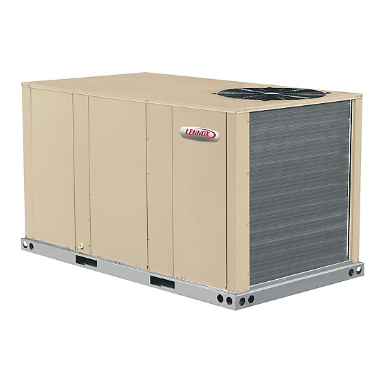
- Page 1 INSTALLATION Litho U.S.A. INSTRUCTIONS ©2015 WARNING KGB/KCB024 2-Ton Improper installation, adjustment, alteration, ser KGB/KCB030 2-1/2-Ton vice or maintenance can cause property damage, personal injury or loss of life. Installation and ser KGA/KCA036 3-Ton vice must be performed by a licensed professional HVAC installer or equivalent, service agency, or the gas supplier 3-Ton...
-
Page 2: Dimensions
KG / KC 024, 030, 036, 048, 060, 072, 074, 090 DIMENSIONS in. - Gas heat section shown 5-5/8 16-1/4 (143) (413) (457) (279) 5 (127) BOTTOM 7 (178) RETURN OPENING CENTER BOTTOM (508) (737) SUPPLY GRAVITY 47 (1192) OPENING BASE 25-3/4 (654) 024 thru 074... -
Page 3: Parts Arrangements
KG 024, 030, 036, 048, 060, 072, 074, 090 PARTS ARRANGEMENT (KGA090 shown) EVAPORATOR REFRIGERANT BLOWER COIL METERING DEVICE TB1 LOW VOLTAGE MOTOR FILTERS (4) CONDENSER TERMINAL BLOCK ECONOMIZER (OPTIONAL) BLOWER CONDENSER COIL CONDENSATE DRAIN COMBUSTION BURNERS AIR INDUCER GAS VALVE COMPRESSOR KC 024, 030, 036, 048, 060, 072, 074, 090 PARTS ARRANGEMENT (KCA090 shown) -
Page 4: Shipping And Packing List
CAUTION IMPORTANT Danger of sharp metallic edges. Can cause injury. The Clean Air Act of 1990 bans the intentional vent Take care and wear protective clothing when ing of refrigerant (CFC's and HCFC's) as of July 1, servicing unit to avoid accidental contact with 1992. -
Page 5: Unit Support
S The heat exchanger, components, duct system, air 3- Frame or supports must be high enough to prevent form moisture from entering unit. filters and evaporator coil must be thoroughly Recommended minimum frame height is 14” cleaned following final construction clean-up. (356mm). -
Page 6: Rigging Unit For Lifting
2- Leave the horizontal return air cover in place. Rigging Unit For Lifting 3- Locate the separately ordered horizontal air Rig unit for lifting by attaching four cables to holes in unit discharge kit. Place the kit panel over the downflow base rail. - Page 7 A trap must be installed between drain connection and an If the unit has hinged panels, two hinge screws must open vent for proper condensate removal. See figure 5 or be removed in addition to the mullion screws. See 6. It is sometimes acceptable to drain condensate onto figure 8.
-
Page 8: Gas Piping
Bottom Drain Connection Connect Gas Piping (Gas Units) 1- Remove the condensate drain mullion. See figure 7. Before connecting field-provided piping, check with gas 2- Lift the front edge of the drain pan and slide pan out company or authorities having jurisdiction for local code of unit. -
Page 9: Pressure Test Gas Piping
PRESSURE TEST GAS LINE BOTTOM ENTRY GAS PIPING COMPLETED TO GAS GROUND VALVE MANUAL MAIN JOINT UNION SHUT-OFF VALVE STREET ELBOW 7” NIPPLE GAS VALVE TO GAS SUPPLY FIGURE 13 2-1/2” NIPPLE MANUAL MAIN SHUT-OFF VALVE DRIP LEG High Altitude Derate Grommets for both gas pipe openings are field provided. - Page 10 CONTROL WIRING 3- Connect thermostat wiring to TB1 terminal board on the lower side of the controls hat section. Wire as A-Thermostat Location shown in figure 14 for electro-mechanical and Room thermostat mounts vertically on a standard 2” X 4” electronic thermostats.
-
Page 11: Blower Operation And Adjustments
B-Determining Unit CFM - Direct Drive Blowers Blower Operation and Adjustments 1- The following measurements must be made with air KG/KC 024 and 030 units are equipped with direct drive filters in place. blowers only. KG/KC 036, 048 and 060 units are equipped 2- With all access panels in place, measure static with either direct drive or belt drive blowers. - Page 12 FIELD-ADJUSTABLE BLOWER SPEEDS - DIRECT DRIVE - 460/575V TAPE BACK AND SECURE HIGH SPEED UNUSED ISOLATION LEAD L1-Terminal COM LOW SPEED 036, 048 UNITS TO CAPACITOR WIRES. L2-Terminal HI L1-Terminal COM L2-Terminal LOW Park isolation lead into terminal HI Do not park isolation lead 1-COM 1-COM...
- Page 13 BLOWER ASSEMBLY TO INCREASE CFM TO DECREASE CFM LOOSEN ALLEN SCREW & TURN PULLEY TURN PULLEY CLOCKWISE COUNTERCLOCKWISE SIDE VIEW LOOSEN ALLEN SCREW TO ADJUST CFM MOTOR ALLEN SCREW PULLEY TO INCREASE BELT TENSION 1-Loosen four bolts securing motor base to mounting frame.
- Page 14 G-Field-Furnished Blower Drives INSTALL BELT For field-furnished blower drives, use belt drive blower tables to determine BHP and RPM required. Reference DRIVER TENSIONER the drive kit specification table and manufacturer's drive PULLEY number table. MEASURE BELT TENSION FORCE DEFLECTION 1/64” PER INCH OF SPAN OR 1.5mm PER 100mm OF SPAN FIGURE 21 ADJUST BELT TENSIONER...
- Page 15 BLOWER DATA - DIRECT DRIVE - KGB024 BLOWER TABLE INCLUDES RESISTANCE FOR BASE UNIT ONLY WITH DRY INDOOR COIL AND AIR FILTERS IN PLACE. FOR ALL UNITS ADD: 1 - Any factory installed options air resistance (larger gas heat section, economizer, wet coil, etc.) See page 41.
- Page 16 BLOWER DATA - DIRECT DRIVE - KGB030 BLOWER TABLE INCLUDES RESISTANCE FOR BASE UNIT ONLY WITH DRY INDOOR COIL AND AIR FILTERS IN PLACE. FOR ALL UNITS ADD: 1 - Any factory installed options air resistance (larger gas heat section, economizer, wet coil, etc.) See page 41. 2 - Any field installed accessories air resistance (duct resistance, diffuser, etc.) See page 41.
- Page 17 BLOWER DATA - DIRECT DRIVE - KGA/KGB036, KGA/KGB048 BLOWER TABLE INCLUDES RESISTANCE FOR BASE UNIT ONLY WITH DRY INDOOR COIL AND AIR FILTERS IN PLACE. FOR ALL UNITS ADD: 1 - Any factory installed options air resistance (larger gas heat section, economizer, wet coil, etc.) See page 41. 2 - Any field installed accessories air resistance (duct resistance, diffuser, etc.) See page 41.
- Page 18 BLOWER DATA - DIRECT DRIVE - KGA060 BLOWER TABLE INCLUDES RESISTANCE FOR BASE UNIT ONLY WITH DRY INDOOR COIL AND AIR FILTERS IN PLACE. FOR ALL UNITS ADD: 1 - Any factory installed options air resistance (larger gas heat section, economizer, wet coil, etc.) See page 41. 2 - Any field installed accessories air resistance (duct resistance, diffuser, etc.) See page 41.
- Page 19 BLOWER DATA - DIRECT DRIVE - KGB060 BLOWER TABLE INCLUDES RESISTANCE FOR BASE UNIT ONLY WITH DRY INDOOR COIL AND AIR FILTERS IN PLACE. FOR ALL UNITS ADD: 1 - Any factory installed options air resistance (larger gas heat section, economizer, wet coil, etc.) See page 41. 2 - Any field installed accessories air resistance (duct resistance, diffuser, etc.) See page 41.
- Page 20 BLOWER DATA - BELT DRIVE - KGA/KGB036 BLOWER TABLE INCLUDES RESISTANCE FOR BASE UNIT ONLY WITH DRY INDOOR COIL AND AIR FILTERS IN PLACE. FOR ALL UNITS ADD: 1 - Any factory installed options air resistance (heat section, economizer, wet coil, etc.). 2 - Any field installed accessories air resistance (duct resistance, diffuser, etc.).
- Page 21 BLOWER DATA - BELT DRIVE - KGA/KGB048 BLOWER TABLE INCLUDES RESISTANCE FOR BASE UNIT ONLY WITH DRY INDOOR COIL AND AIR FILTERS IN PLACE. FOR ALL UNITS ADD: 1 - Any factory installed options air resistance (heat section, economizer, wet coil, etc.). 2 - Any field installed accessories air resistance (duct resistance, diffuser, etc.).
- Page 22 BLOWER DATA - BELT DRIVE - KGA060 BLOWER TABLE INCLUDES RESISTANCE FOR BASE UNIT ONLY WITH DRY INDOOR COIL AND AIR FILTERS IN PLACE. FOR ALL UNITS ADD: 1 - Any factory installed options air resistance (heat section, economizer, wet coil, etc.). 2 - Any field installed accessories air resistance (duct resistance, diffuser, etc.).
- Page 23 BLOWER DATA - BELT DRIVE - KGB060 BLOWER TABLE INCLUDES RESISTANCE FOR BASE UNIT ONLY WITH DRY INDOOR COIL AND AIR FILTERS IN PLACE. FOR ALL UNITS ADD: 1 - Any factory installed options air resistance (heat section, economizer, wet coil, etc.). 2 - Any field installed accessories air resistance (duct resistance, diffuser, etc.).
- Page 24 BLOWER DATA - BELT DRIVE - DOWNFLOW - KGA072, KGB072 & 074 BLOWER TABLE INCLUDES RESISTANCE FOR BASE UNIT ONLY WITH DRY INDOOR COIL AND AIR FILTERS IN PLACE. FOR ALL UNITS ADD: 1 - Any factory installed options air resistance (heat section, economizer, wet coil, etc.). 2 - Any field installed accessories air resistance (duct resistance, diffuser, etc.).
- Page 25 BLOWER DATA - BELT DRIVE - HORIZONTAL - KGA072, KGB072 & 074 BLOWER TABLE INCLUDES RESISTANCE FOR BASE UNIT ONLY WITH DRY INDOOR COIL AND AIR FILTERS IN PLACE. FOR ALL UNITS ADD: 1 - Any factory installed options air resistance (heat section, economizer, wet coil, etc.). 2 - Any field installed accessories air resistance (duct resistance, diffuser, etc.).
- Page 26 BLOWER DATA - BELT DRIVE - KGA090 - DOWNFLOW BLOWER TABLE INCLUDES RESISTANCE FOR BASE UNIT ONLY WITH DRY INDOOR COIL AND AIR FILTERS IN PLACE. FOR ALL UNITS ADD: 1 - Any factory installed options air resistance (heat section, economizer, wet coil, etc.). 2 - Any field installed accessories air resistance (duct resistance, diffuser, etc.).
- Page 27 BLOWER DATA - BELT DRIVE - KGA090 - HORIZONTAL BLOWER TABLE INCLUDES RESISTANCE FOR BASE UNIT ONLY WITH DRY INDOOR COIL AND AIR FILTERS IN PLACE. FOR ALL UNITS ADD: 1 - Any factory installed options air resistance (heat section, economizer, wet coil, etc.). 2 - Any field installed accessories air resistance (duct resistance, diffuser, etc.).
- Page 28 BLOWER DATA - DIRECT DRIVE - KCB024 BLOWER TABLE INCLUDES RESISTANCE FOR BASE UNIT ONLY WITH DRY INDOOR COIL AND AIR FILTERS IN PLACE. FOR ALL UNITS ADD: 1 - Any factory installed options air resistance (economizer, wet coil, etc.) See page 41 . 2 - Any field installed accessories air resistance (electric heat, duct resistance, diffuser, etc.) See page 41.
- Page 29 BLOWER DATA - DIRECT DRIVE - KCB030 BLOWER TABLE INCLUDES RESISTANCE FOR BASE UNIT ONLY WITH DRY INDOOR COIL AND AIR FILTERS IN PLACE. FOR ALL UNITS ADD: 1 - Any factory installed options air resistance (economizer, wet coil, etc.) See page 41. 2 - Any field installed accessories air resistance (electric heat, duct resistance, diffuser, etc.) See page 41.
- Page 30 BLOWER DATA - DIRECT DRIVE - KCA/KCB036, KCA/KCB048 BLOWER TABLE INCLUDES RESISTANCE FOR BASE UNIT ONLY WITH DRY INDOOR COIL AND AIR FILTERS IN PLACE. FOR ALL UNITS ADD: 1 - Any factory installed options air resistance (economizer, wet coil, etc.) See “BLOWER DATA” on page 41. 2 - Any field installed accessories air resistance (electric heat, duct resistance, diffuser, etc.) See “BLOWER DATA”...
- Page 31 BLOWER DATA - DIRECT DRIVE - KCA060 BLOWER TABLE INCLUDES RESISTANCE FOR BASE UNIT ONLY WITH DRY INDOOR COIL AND AIR FILTERS IN PLACE. FOR ALL UNITS ADD: 1 - Any factory installed options air resistance (economizer, wet coil, etc.) See”BLOWER DATA” on page 41. 2 - Any field installed accessories air resistance (electric heat, duct resistance, diffuser, etc.) See”BLOWER DATA”...
- Page 32 BLOWER DATA - DIRECT DRIVE - KCB060 BLOWER TABLE INCLUDES RESISTANCE FOR BASE UNIT ONLY WITH DRY INDOOR COIL AND AIR FILTERS IN PLACE. FOR ALL UNITS ADD: 1 - Any factory installed options air resistance (economizer, wet coil, etc.) See page 41. 2 - Any field installed accessories air resistance (electric heat, duct resistance, diffuser, etc.) See page 41.
- Page 33 BLOWER DATA - BELT DRIVE - KCA/KCB036 BLOWER TABLE INCLUDES RESISTANCE FOR BASE UNIT ONLY WITH DRY INDOOR COIL AND AIR FILTERS IN PLACE. FOR ALL UNITS ADD: 1 - Any factory installed options air resistance (economizer, wet coil, etc.) See page 41. 2 - Any field installed accessories air resistance (electric heat, duct resistance, diffuser, etc.) See page 41.
- Page 34 BLOWER DATA - BELT DRIVE - KCA/KCB048 BLOWER TABLE INCLUDES RESISTANCE FOR BASE UNIT ONLY WITH DRY INDOOR COIL AND AIR FILTERS IN PLACE. FOR ALL UNITS ADD: 1 - Any factory installed options air resistance (economizer, wet coil, etc.) See page 41. 2 - Any field installed accessories air resistance (electric heat, duct resistance, diffuser, etc.) See page 41.
- Page 35 BLOWER DATA - BELT DRIVE - KCA060 BLOWER TABLE INCLUDES RESISTANCE FOR BASE UNIT ONLY WITH DRY INDOOR COIL AND AIR FILTERS IN PLACE. FOR ALL UNITS ADD: 1 - Any factory installed options air resistance (economizer, wet coil, etc.) See page 41. 2 - Any field installed accessories air resistance (electric heat, duct resistance, diffuser, etc.) See page 41.
- Page 36 BLOWER DATA - BELT DRIVE - KCB060 BLOWER TABLE INCLUDES RESISTANCE FOR BASE UNIT ONLY WITH DRY INDOOR COIL AND AIR FILTERS IN PLACE. FOR ALL UNITS ADD: 1 - Any factory installed options air resistance (economizer, wet coil, etc.) See page 41. 2 - Any field installed accessories air resistance (electric heat, duct resistance, diffuser, etc.) See page 41.
- Page 37 BLOWER DATA - BELT DRIVE - KCA072, KCB072 & 074 - DOWNFLOW BLOWER TABLE INCLUDES RESISTANCE FOR BASE UNIT ONLY WITH DRY INDOOR COIL AND AIR FILTERS IN PLACE. FOR ALL UNITS ADD: 1 - Any factory installed options air resistance (economizer, wet coil, etc.) See page 41. 2 - Any field installed accessories air resistance (electric heat, duct resistance, diffuser, etc.) See page 41.
- Page 38 BLOWER DATA - BELT DRIVE - KCA072, KCB072 & 074 - HORIZONTAL BLOWER TABLE INCLUDES RESISTANCE FOR BASE UNIT ONLY WITH DRY INDOOR COIL AND AIR FILTERS IN PLACE. FOR ALL UNITS ADD: 1 - Any factory installed options air resistance (economizer, wet coil, etc.) See page 41. 2 - Any field installed accessories air resistance (electric heat, duct resistance, diffuser, etc.) See page 41.
- Page 39 BLOWER DATA - BELT DRIVE - KCA090 - DOWNFLOW BLOWER TABLE INCLUDES RESISTANCE FOR BASE UNIT ONLY WITH DRY INDOOR COIL AND AIR FILTERS IN PLACE. FOR ALL UNITS ADD: 1 - Any factory installed options air resistance (economizer, wet coil, etc.) See page 41. 2 - Any field installed accessories air resistance (electric heat, duct resistance, diffuser, etc.) See page 41.
- Page 40 BLOWER DATA - BELT DRIVE - KCA090 - HORIZONTAL BLOWER TABLE INCLUDES RESISTANCE FOR BASE UNIT ONLY WITH DRY INDOOR COIL AND AIR FILTERS IN PLACE. FOR ALL UNITS ADD: 1 - Any factory installed options air resistance (economizer, wet coil, etc.) See page 41. 2 - Any field installed accessories air resistance (electric heat, duct resistance, diffuser, etc.) See page 41.
-
Page 41: Blower Data
BLOWER DATA BELT DRIVE KIT SPECIFICATIONS Blower Motor Choice (HP) Model Drive Kit No. RPM Range Nominal Maximum Nominal Maximum Nominal Maximum Nominal Maximum 673 - 1010 rpm 0.75 0.86 1.15 897 - 1346 rpm 745 - 1117 rpm 0.75 0.86 1.15 1071 - 1429 rpm... -
Page 42: Cooling Start-Up
TABLE 5 DRIVE COMPONENT MANUFACTURER'S NUMBERS DRIVE COMPONENTS MOTOR PULLEY BLOWER PULLEY BELTS Browning No. OEM Part No. Browning No. OEM Part No. Browning No. OEM Part No. Drive No. 1VP34 X 7/8 31K6901 AK54 X 1 100244-19 100245-17 1VP34 X 7/8 31K6901 AK49 X 1 100244-18... - Page 43 C-Refrigerant Charge and Check - Fin/Tube Coil TABLE 8 KGA 036S -4 & HIGHER; KCA 036S -3 & HIGHER KGA/KCA 036 to 060 NORMAL OPERATING PRESSURES WARNING-Do not exceed nameplate charge under Outdoor Coil Discharge Suction + 5 any condition. Entering Air Temp +10 psig psig...
- Page 44 TABLE 12 If weighing facilities are not available, or to check the KGA 060S -5 & HIGHER; KCA 060S -4 & HIGHER charge, use the following procedure: NORMAL OPERATING PRESSURES IMPORTANT - Charge unit in standard cooling mode. Outdoor Coil Discharge Suction + 5 Entering Air Temp...
- Page 45 TABLE 15 KGB/KCB030 Normal Operating Pressures Outdoor Coil Entering Air Temperature 65 °F 75 °F 85 °F 95 °F 105 °F 115 °F Suct Disc Suct Disc Suct Disc Suct Disc Suct Disc Suct Disc (psig) (psig) (psig) (psig) (psig) (psig) (psig) (psig)
- Page 46 TABLE 20 KGB/KCB 074S & H Normal Operating Pressures Outdoor Coil Entering Air Temperature 65 °F 75 °F 85 °F 95 °F 105 °F 115 °F Suct Disc Suct Disc Suct Disc Suct Disc Suct Disc Suct Disc (psig) (psig) (psig) (psig) (psig)
- Page 47 KGB/KCB 030 Charging Curves Outdoor Temperature (°F) 115° 105° 95° 85° 75° 65° Suction Pressure (psig) KGB/KCB 036 Charging Curves Outdoor Temperature (°F) 115° 105° 95° 85° 75° 65° Suction Pressure (psig) Page 47 507348-04 12/2015...
- Page 48 KGB/KCB 048 Charging Curves Outdoor Temperature (°F) 115° 105° 95° 85° 75° 65° Suction Pressure (psig) KGB/KCB 060 Charging Curves Outdoor Temperature (°F) 115° 105° 95° 85° 75° 65° Suction Pressure (psig) Page 48 KG/KC 024, 030, 036, 048, 060, 072, 074, 090...
- Page 49 KGA/KCA 072 Charging Curves Outdoor Temperature (°F) 115° 105° 95° 85° 75° 65° Suction Pressure (psig) KGB/KCB074S & H Charging Curves Outdoor Temperature (°F) 115° 105° 95° 85° 75° 65° Suction Pressure (psig) Page 49 507348-04 12/2015...
- Page 50 KGA/KCA 090 Charging Curves Outdoor Temperature (°F) 115° 105° 95° 85° 75° 65° Suction Pressure (psig) F-Compressor Controls S4 is wired in series with the compressor contactor coil and is located on the compressor discharge line. See unit wiring diagram to determine which controls are used on each unit.
-
Page 51: Gas Heat Start-Up
This unit is equipped with an automatic spark ignition Gas Heat Start-Up (Gas Units) system. There is no pilot. In case of a safety shutdown, move thermostat switch to OFF and return the thermostat FOR YOUR SAFETY READ BEFORE LIGHTING switch to HEAT to reset ignition control. -
Page 52: Heating Operation And Adjustments
5- Move gas valve switch to OFF. See figure 24 or 25. 5- If flame is not detected after first ignition trial, ignition control will repeat steps 3 and 4 two more times 6- Wait five (5) minutes to clear out any gas. If you then before locking out the gas valve. -
Page 53: Service
Service REMOVE FILTERS The unit should be inspected once a year by a qualified service technician. CAUTION Label all wires prior to disconnection when servic ing controls. Wiring errors can cause improper and dangerous operation. Verify proper operation after servicing. PULL TO REMOVE FILTERS... - Page 54 5- Locate the ignitor under the right burner. Check D-Combustion Air Inducer (Gas Units) ignitor spark gap with appropriately sized twist drills A combustion air proving switch checks combustion air or feeler gauges. See figure 28. inducer operation before allowing power to the gas controller.
- Page 55 H-Compressor Flush coil and condensate drain with water taking care not to get insulation, filters and return air ducts wet. If Interlink compressor replacement is necessary, call 1-800-4-LENNOX (1-800-453-6669). G-Condenser Coil IMPORTANT All-Aluminum Coils - Some scroll compressors have an internal vacu...
- Page 56 J-Supply Air Blower Replacement 4- Reinstall blower in channels. Secure blower in place with seven retained screws. -072H, -074H and -090 Units Only - 5- Replace L-bracket and reinstall screws from the top, 1- Peel the rubber seal off of the L-bracket on the blower 6- Replace rubber seal.