Advertisement
Quick Links
E2017
WARNING
Improper installation, adjustment, alteration, ser
vice or maintenance can cause property damage,
personal injury or loss of life. Installation and ser
vice must be performed by a licensed professional
HVAC installer or equivalent or service agency.
CAUTION
As with any mechanical equipment, contact with
sharp sheet metal edges can result in personal in
jury. Take care while handling this equipment and
wear gloves and protective clothing.
Table Of Contents
Dimensions
. . . . . . . . . . . . . . . . . . . . . . . . . . . . . . . . .
Shipping and Packing List
. . . . . . . . . . . . . . . . . . . .
General
. . . . . . . . . . . . . . . . . . . . . . . . . . . . . . . . . . . .
Requirements
. . . . . . . . . . . . . . . . . . . . . . . . . . . . . . .
Unit Support
. . . . . . . . . . . . . . . . . . . . . . . . . . . . . . . .
Duct Connection
. . . . . . . . . . . . . . . . . . . . . . . . . . . .
RETAIN THESE INSTRUCTIONS FOR FUTURE REFERENCE
KDB024, 036, 048, 060 PARTS ARRANGEMENT
FILTERS
ECONOMIZER
(OPTIONAL)
INDOOR
TXV
CONDENSATE
DRAIN
COMBUSTION
AIR INDUCER
BURNERS
Page 2
Page 3
Page 3
Page 3
Page 4
Page 5
EVAPORATOR
COIL
TB1 LOW VOLTAGE
GAS VALVE
TERMINAL BLOCK
INSTALLATION
INSTRUCTIONS
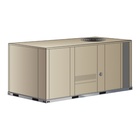
KDB024
(2 TON)
KDB036
(3 TON)
KDB048
(4 TON)
KDB060
(5 TON)
ROOFTOP PACKAGED UNITS
507626-01
04/2017
Supersedes 8/2016
Rigging Unit For Lifting
. . . . . . . . . . . . . . . . . . . . . . .
Condensate Drains
. . . . . . . . . . . . . . . . . . . . . . . . . .
Electrical Connections
. . . . . . . . . . . . . . . . . . . . . . .
Unit Power-Up
. . . . . . . . . . . . . . . . . . . . . . . . . . . . . .
Blower Operation and Adjustments
Defrost Control Board
. . . . . . . . . . . . . . . . . . . . . . . .
Service
. . . . . . . . . . . . . . . . . . . . . . . . . . . . . . . . . . . .
CONDENSER
BLOWER
FAN
REVERSING
COMPRESSOR
VALVE
Page 5
Page 6
Page 9
Page 9
. . . . . . . . . . . .
Page 10
Page 30
Page 33
OUTDOOR
TXV
CONDENSER
COIL
Advertisement

Related Manuals for Lennox KDB024


Summary of Contents for Lennox KDB024
- Page 1 ........Page 33 RETAIN THESE INSTRUCTIONS FOR FUTURE REFERENCE KDB024, 036, 048, 060 PARTS ARRANGEMENT EVAPORATOR CONDENSER...
- Page 2 KDB024, 030, 036, 048, 060 DIMENSIONS 5-5/8 16-1/4 (143) (413) (457) (279) 5 (127) BOTTOM 7 (178) RETURN OPENING CENTER BOTTOM (508) (737) SUPPLY GRAVITY 47 (1192) OPENING BASE 25-3/4 (654) 024 thru 074 38-3/4 (984) 090 9-1/2 6-5/8 (241)
- Page 3 FIGURE 1 KDB036, 048, and 060 3-phase units are equipped with two-speed, belt or direct drive supply air blowers. KDB024, 036, 048 and 060 1-phase units are equipped with variable speed, direct drive blowers. These units will 1 Unit provide supply air at lower speeds when cooling demand in.(mm)
-
Page 4: Unit Support
Use of this unit as a construction heater or air conditioner Unit Support is not recommended during any phase of construction. NOTE - Securely fasten roof frame to roof per local codes. Very low return air temperatures, harmful vapors and operation of the unit with clogged or misplaced filters will CAUTION damage the unit. -
Page 5: Duct Connection
3- Top of support slab should be at least 4” (102mm) Horizontal Air Discharge above the finished grade and located so no run-off Unit is shipped with panels covering the horizontal supply water from higher ground can collect around the unit. and return air openings. -
Page 6: Condensate Drains
Units are shipped with the drain coupling facing the front Condensate Drains of the unit. Condensate can be drained from the back or Make drain connection to the 1” N.P.T. drain coupling bottom of the unit with the following modifications. The provided on unit. - Page 7 REMOVE DRAIN PAN BOTTOM CONDENSATE DRAIN CAUTION: Be careful not to damage the coupling threads when drilling the hole. DRILL A PILOT HOLE IN CENTER OF COUPLING DRAIN PAN FIGURE 9 After drilling the pilot hole, drill a 7/8” hole from the inside of the pan.
- Page 8 After all connections have been made, check all piping OUTSIDE OF UNIT GAS PIPE CONNECTION connections for gas leaks. Also check existing unit gas connections up to the gas valve; loosening may occur during installation. Use a leak detection solution or other preferred means.
-
Page 9: Electrical Connections
electronic thermostats. If using other temperature Electrical Connections control devices or energy management systems see POWER SUPPLY instructions and wiring diagram provided by Do not apply power or close disconnect switch until manufacturer. installation is complete. Refer to start-up directions. Refer to unit nameplate for minimum circuit ampacity and maximum fuse size. - Page 10 2- Remove and retain screws on either side of sliding Blower Operation and Adjustments frame. Pull frame toward outside of unit. KD 024 units are equipped with multi-tap ECM, direct 3- Slide frame back into original position when finished drive blowers only. servicing.
- Page 11 4- Use direct drive blower tables, the measured static 4- The blower RPM can be adjusted at the motor pulley. pressure and the factory-set blower speed to Loosen Allen screw and turn adjustable pulley determine CFM. If CFM is lower or higher than the clockwise to increase CFM.
- Page 12 BLOWER ASSEMBLY TO INCREASE CFM TO DECREASE CFM LOOSEN ALLEN SCREW & TURN PULLEY TURN PULLEY CLOCKWISE COUNTERCLOCKWISE SIDE VIEW LOOSEN ALLEN SCREW TO ADJUST CFM MOTOR ALLEN SCREW PULLEY TO INCREASE BELT TENSION 1-Loosen four bolts securing motor base to mounting frame.
- Page 13 BLOWER DATA - DIRECT DRIVE - HIGH EFFICIENCY 2 TON BLOWER TABLE INCLUDES RESISTANCE FOR BASE UNIT ONLY WITH DRY INDOOR COIL AND AIR FILTERS IN PLACE. FOR ALL UNITS ADD: 1 - Any factory installed options air resistance (economizer, wet coil, etc.) See page 23. 2 - Any field installed accessories air resistance (electric heat, duct resistance, diffuser, etc.) See page 23.
- Page 14 BLOWER DATA - DIRECT DRIVE - HIGH EFFICIENCY 3 TON BLOWER TABLE INCLUDES RESISTANCE FOR BASE UNIT ONLY WITH DRY INDOOR COIL AND AIR FILTERS IN PLACE. FOR ALL UNITS ADD: 1 - Any factory installed options air resistance (economizer, wet coil, etc.) See page 23. 2 - Any field installed accessories air resistance (electric heat, duct resistance, diffuser, etc.) See page 23.
- Page 15 BLOWER DATA - DIRECT DRIVE - HIGH EFFICIENCY 4 TON BLOWER TABLE INCLUDES RESISTANCE FOR BASE UNIT ONLY WITH DRY INDOOR COIL AND AIR FILTERS IN PLACE. FOR ALL UNITS ADD: 1 - Any factory installed options air resistance (economizer, wet coil, etc.) See page 23. 2 - Any field installed accessories air resistance (electric heat, duct resistance, diffuser, etc.) See page 23.
- Page 16 BLOWER DATA - DIRECT DRIVE - HIGH EFFICIENCY 5 TON BLOWER TABLE INCLUDES RESISTANCE FOR BASE UNIT ONLY WITH DRY INDOOR COIL AND AIR FILTERS IN PLACE. FOR ALL UNITS ADD: 1 - Any factory installed options air resistance (economizer, wet coil, etc.) See page 23. 2 - Any field installed accessories air resistance (electric heat, duct resistance, diffuser, etc.) See page 23.
- Page 17 BLOWER DATA - BELT DRIVE 3 TON BLOWER TABLE INCLUDES RESISTANCE FOR BASE UNIT ONLY WITH DRY INDOOR COIL AND AIR FILTERS IN PLACE. FOR ALL UNITS ADD: 1 - Any factory installed options air resistance (larger gas heat section, economizer, wet coil, etc.). 2 - Any field installed accessories air resistance (duct resistance, diffuser, etc.).
- Page 18 BLOWER DATA - BELT DRIVE 3 TON BLOWER TABLE INCLUDES RESISTANCE FOR BASE UNIT ONLY WITH DRY INDOOR COIL AND AIR FILTERS IN PLACE. FOR ALL UNITS ADD: 1 - Any factory installed options air resistance (larger gas heat section, economizer, wet coil, etc.). 2 - Any field installed accessories air resistance (duct resistance, diffuser, etc.).
- Page 19 BLOWER DATA - BELT DRIVE 4 TON BLOWER TABLE INCLUDES RESISTANCE FOR BASE UNIT ONLY WITH DRY INDOOR COIL AND AIR FILTERS IN PLACE. FOR ALL UNITS ADD: 1 - Any factory installed options air resistance (larger gas heat section, economizer, wet coil, etc.). 2 - Any field installed accessories air resistance (duct resistance, diffuser, etc.).
- Page 20 BLOWER DATA - BELT DRIVE 4 TON BLOWER TABLE INCLUDES RESISTANCE FOR BASE UNIT ONLY WITH DRY INDOOR COIL AND AIR FILTERS IN PLACE. FOR ALL UNITS ADD: 1 - Any factory installed options air resistance (larger gas heat section, economizer, wet coil, etc.). 2 - Any field installed accessories air resistance (duct resistance, diffuser, etc.).
- Page 21 BLOWER DATA - BELT DRIVE 5 TON BLOWER TABLE INCLUDES RESISTANCE FOR BASE UNIT ONLY WITH DRY INDOOR COIL AND AIR FILTERS IN PLACE. FOR ALL UNITS ADD: 1 - Any factory installed options air resistance (larger gas heat section, economizer, wet coil, etc.). 2 - Any field installed accessories air resistance (duct resistance, diffuser, etc.).
- Page 22 BLOWER DATA - BELT DRIVE 5 TON BLOWER TABLE INCLUDES RESISTANCE FOR BASE UNIT ONLY WITH DRY INDOOR COIL AND AIR FILTERS IN PLACE. FOR ALL UNITS ADD: 1 - Any factory installed options air resistance (larger gas heat section, economizer, wet coil, etc.). 2 - Any field installed accessories air resistance (duct resistance, diffuser, etc.).
- Page 23 BLOWER DATA BELT DRIVE KIT SPECIFICATIONS Model Motor HP No. of Drive Kits and RPM Range Speeds Nominal Maximum 0.75 0.86 low 449-673 - - - - - - - - - - - - - - - high 673-1010 1.15 - - - - - -...
- Page 24 TABLE 3 MANUFACTURER'S NUMBERS DRIVE COMPONENTS MOTOR PULLEY BLOWER PULLEY BELTS Browning No. OEM Part No. Browning No. OEM Part No. Browning No. OEM Part No. Drive No. 1VP34 X 3/8 31K6901 AK54 X 1 100244-19 100245-17 1VP34 X 3/8 31K6901 AK49 X 1 100244-18...
- Page 25 NOTE - System charging is not recommended below 7- Example KDB024: At 95°F outdoor ambient and a 60_F (15_C). In temperatures below 60_F (15_C), the charge must be weighed into the system.
- Page 26 TABLE 5 KDB024H Normal Operating Pressures Outdoor Coil Entering Air Temperature 65 °F 75 °F 85 °F 95 °F 105 °F 115 °F Suct Disc Suct Disc Suct Disc Suct Disc Suct Disc Suct Disc (psig) (psig) (psig) (psig) (psig) (psig) (psig) (psig)
- Page 27 KDB 024H Charging Curves Outdoor Temperature (°F) 115° 105° 95° 85° 75° 65° Suction Pressure (psig) KDB 036H Charging Curves Outdoor Temperature (°F) 115° 105° 95° 85° 75° 65° Suction Pressure (psig) Page 27...
- Page 28 KDB 048H Charging Curves Outdoor Temperature (°F) 115° 105° 95° 85° 75° 65° Suction Pressure (psig) KDB 060H Charging Curves Outdoor Temperature (°F) 115° 105° 95° 85° 75° 65° Suction Pressure (psig) Page 28...
- Page 29 D - Compressor Controls a defrost cycle begins and operates for 14 minutes. The defrost switch can terminate the defrost cycle See unit wiring diagram to determine which controls are before the 14 minutes elapses if liquid line used in each unit. Optional controls are identified on temperature reaches 70°F (21°C).
-
Page 30: Defrost Control Board
Defrost Control Board DEFROST CONTROL BOARD CMC1 DEFROST TEMPERATURE TERMINATION JUMPER: The defrost control ensures that the heat pump outdoor 100135-06: 50 F(10 coil does not ice excessively during the heating mode. The defrost control uses input from a defrost switch on 100269 series defrost control boards. - Page 31 This unit is equipped with an automatic spark ignition Gas Heat Start-Up system. There is no pilot. In case of a safety shutdown, move thermostat switch to OFF and return the thermostat FOR YOUR SAFETY READ BEFORE LIGHTING switch to HEAT to reset ignition control. WARNING A-Placing Unit In Operation Electric shock hazard.
- Page 32 12- Spark ignitor energizes and gas valve solenoid opens. WHITE RODGERS 36J54 GAS VALVE Two-Stage 13- Spark ignites gas, ignition sensor proves the flame and combustion continues. MANIFOLD HIGH FIRE PRESSURE TAP ADJUSTMENT 14- If flame is not detected after first ignition trial, ignition control will repeat steps 3 and 4 two more times before locking out the gas valve.
- Page 33 Unit Filter Size - in. (mm) Inspect and clean coil at beginning of each cooling and KDB024, 036 16 X 20 X 2 (406 X 508 X 51) heating season. Clean using mild detergent or commercial coil cleanser. Flush coil and condensate...
- Page 34 IGNITOR WARNING SPARK GAP This product contains a chemical known to the SHOULD BE 1/8” State of California to cause cancer, birth defects, or (3mm) other reproductive harm. G-Burners Periodically examine burner flames proper appearance during the heating season. Before each heating season examine the burners for any deposits or blockage which may have occurred.
- Page 35 16- Return combustion air inducer motor and vent HEAT EXCHANGER ASSEMBLY connector to original location and secure with retained screws. It is recommended that the HEAT combustion air inducer gasket be replaced during EXCHANGER reassembly. TUBE 17- Clean combustion air inlet louvers on heat access COMBUSTION panel using a small brush.