Advertisement
Table of Contents
- 1 Table of Contents
- 2 Parts List
- 3 Safety Considerations
- 4 System Requirements
- 5 Dimensions
- 6 Clearances
- 7 Installation Tips
- 8 Indoor Unit Installation
- 9 Outdoor Unit Installation
- 10 Install All Power and Interconnecting Wiring to Outdoor Units
- 11 Electrical Data
- 12 Connection Diagrams
- 13 Remote Control Installation
- 14 System Vacuum and Charge
- 15 Start- -Up
- 16 Troubleshooting
- Download this manual
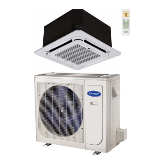
40MBC / 38MAQ
Cassette Ductless Split System
Sizes 09 to 18
NOTE: Read the entire instruction manual before starting the
installation.
Installation Instructions
TABLE OF CONTENTS
. . . . . . . . . . . . . . . . . . . . . . . . . . . . . . . . . . . . . . .
. . . . . . . . . . . . . . . . . . . . . . . . . . . . . . . . . . . . . .
. . . . . . . . . . . . . . . . . . . . . . . . . . . . . . . . . . . . .
. . . . . . . . . . . . . . . . . . . . . . . . . . . . . . . .
. . . . . . . . . . . . . . . . . . . . . . . . . . . . . .
. . . . . . . . . . . . . . . . . . . . . . . . . . . . . . .
. . . . . . . . . . . . . . . . . . . . . . . . . . . . . . . . . . . . . . . .
. . . . . . . . . . . . . . . . . . . . . . . . . . . . . .
. . . . . . . . . . . . . . . . . . . . . . . . .
. . . . . . . . . . . . . . . . . . . . . . . . . . .
. . . . . . . . . . . . . . . . . . . . . . .
. . . . . . . . . . . . . . . . . . . .
. . . . . . . . . . . . . . . . . . . . . . . . .
. . . . . . . . . . . . . . . . .
. . . . . . . . . . . . . . . . . . .
PAGE
2
3
4
5
7
9
9
15
15
16
16
17
17
18
19
Advertisement
Table of Contents

Related Manuals for Carrier 40MBC/38MAQ


Summary of Contents for Carrier 40MBC/38MAQ
-
Page 1: Table Of Contents
40MBC / 38MAQ Cassette Ductless Split System Sizes 09 to 18 Installation Instructions TABLE OF CONTENTS PAGE PARTS LIST ........SAFETY CONSIDERATIONS . -
Page 2: Parts List
PARTS LIST A150633 Fig. 1 --- Parts List Note: --- If the outdoor unit is higher than the indoor unit, prevent rain from flowing into the indoor unit along the connection pipe by creating a downward arc in the connection pipe before it enters the wall to the indoor unit. This will ensure that rain drips from the connection pipe before entering the wall. --- Piping and the interconnecting wiring are field supplied. -
Page 3: Safety Considerations
SAFETY CONSIDERATIONS WARNING Installing, starting up, and servicing air- -conditioning equipment can be hazardous due to system pressures, electrical components, ELECTRICAL SHOCK HAZARD and equipment location (roofs, elevated structures, etc.). Failure to follow this warning could result in personal Only trained, qualified installers and service mechanics should injury or death. -
Page 4: System Requirements
SYSTEM REQUIREMENTS Allow sufficient space for airflow and servicing unit. See Fig. 5 for minimum required distances between unit and walls or ceilings. Piping IMPORTANT: Both refrigerant lines must be insulated separately. S Minimum refrigerant line length between the indoor and outdoor units is 10 ft. (3 m). S Table 1 lists the maximum lengths. -
Page 5: Dimensions
DIMENSIONS - - INDOOR Fig. 2 --- Indoor Unit Table 2—Dimensions Indoor UNIT SIZE BODY PANEL BODY PANEL BODY PANEL Dimensions Height in(mm) 10.24 (260) 1.97 (50) 10.24 (260) 1.97 (50) 10.24 (260) 1.97 (50) Width in(mm) 22.44 (570) 25.47 (647) 22.44 (570) 25.47 (647) 22.44 (570) - Page 6 DIMENSIONS - - OUTDOOR Fig. 3 --- Outdoor Unit Table 3—Dimensions Outdoor OPERATING WEIGHT MODEL W in (mm) D in (mm) H in (mm) L1 in (mm) L2 in (mm) lb (kg) 9K/12K 32.0 (810) 12.2 (310) 22.0 (558) 20.9 (530) 11.4 (290) 82.5 (37.4) 32.3 (845)
-
Page 7: Clearances
CLEARANCES - - INDOOR Fig. 4 --- Cassette Unit Clearance... - Page 8 CLEARANCES - - OUTDOOR Air-inlet Air-outlet A07894 Fig. 5 --- Outdoor Unit Clearance Table 4—Outdoor Unit Clearance Dimensions MINIMUM VALUE UNIT in. (mm) 24 (610) 24 (610) 24 (610) 4 (101) 4 (101)
-
Page 9: Installation Tips
INSTALLATION TIPS IMPORTANT: Drilling holes in the ceiling must be performed by professional personnel. Indoor Unit Installation locations include: S A location where there are no obstacles near the inlet and outlet areas. S A location which can bear the weight of the indoor unit is critical. - Page 10 INDOOR UNIT MAIN BODY INSTALLATION (1.) Nut (field supply) (2.) Washer (field supply) 1. Prepare the ceiling opening needed for installation where applicable (for existing ceilings). (3.) Hanger bracket a. Create the ceiling opening required for installation. From the (4.) Double nuts (field supply, tighten) side of the opening to the casing outlet, implement the 4.
- Page 11 DRAIN PIPING WORK DRAINAGE HOSE Drain Piping Installation IMPORTANT: Observe all local sanitary codes when installing condensate drains. Install the drain piping as shown in Fig. 14 and take steps to eliminate condensation. Improperly rigged piping could lead to 1. Install the drain hose. leaks and eventually wet furniture and belongings.
- Page 12 1. Install the drain hose according to the following process if several drain hoses join together. Fig. 21 --- Slant Gradient 2. Check the smoothness of the drain after the installation. Unit: in/mm 3. Check the drain state by draining 36 3/5 in. 3 (600 cc) of water slowly from the outlet vent or test hole.
- Page 13 INSTALLATION OF THE DECORATION PANEL 3. After installing the decoration panel, ensure there is no space between the unit body and the decoration panel. Otherwise air Detach the intake grill may leak through the gap and cause dewdrops (see Fig. 27). 1.
- Page 14 Grille Louver Motor Power. Grille Display 5 Pin Port 10 Pin Port Wired Remote Controller Grille Display. (Available as Accessory) 10 pin Molex plug to be 5 Pin Molex plug to be connected to Control Board. connected to Wired Controller’s cable Grille Louver Motor Power.
-
Page 15: Outdoor Unit Installation
OUTDOOR UNIT INSTALLATION Table 5— Tightening Torque Tightening Torque Pipe Diameter 1. Use a rigid base to support the unit in a level position. Inch (mm) Ft- -lb N- -m 2. Locate the outdoor unit and connect the piping and wiring. Ø1/4”... -
Page 16: Electrical Data
ELECTRICAL DATA Table 6—Electrical Data COMPRESSOR OUTDOOR FAN INDOOR FAN UNIT OPER. VOLTAGE MAX FUSE SIZE MAX / MIN* CB AMP V/PH/HZ V/PH/HZ V/PH/HZ 0.42 0.053 253 / 187 208--- 230/1/60 208--- 230/1/60 0.42 0.053 208--- 230/1/60 0.146 0.061 0.85 0.067 *Permissible limits of the voltage range at which the unit will operate satisfactorily. -
Page 17: Remote Control Installation
REMOTE CONTROL INSTALLATION Manifold Gage Mounting Bracket (if installed on the wall) 1. Use the two screws supplied with the control to attach the 500 microns mounting bracket to the wall in a location selected by the Low side valve customer and within operating range. -
Page 18: Start- -Up
SYSTEM CHECKS EVACUATE 1. Conceal the tubing where possible. BREAK VACUUM WITH DRY NITROGEN 2. Ensure the drain tube slopes downward along its entire WAIT length. 3. Ensure all tubing and connections are properly insulated. EVACUATE 4. Fasten the tubes to the outside wall, when possible. BREAK VACUUM WITH DRY NITROGEN 5. -
Page 19: Troubleshooting
TROUBLESHOOTING For ease of service, the systems are equipped with diagnostic code display panel or the front of the unit. If possible, always check the display LEDs on both the indoor and outdoor units. The outdoor diagnostic codes displayed on the indoor unit first. diagnostic display consists of two LEDs (Red and Green) on the The diagnostic codes displayed in the indoor and outdoor units are outdoor unit board and is limited to a few errors. - Page 20 Catalog No: 40MBC ---38MAQ---02SI Copyright 2015 Carrier Corporation S 7310 W. Morris St. S Indianapolis, IN 46231 Edition Date: 10/15 Replaces: 40MBC--- 01SI Manufacturer reserves the right to change, at any time, specifications and designs without notice and without obligations.