Carrier 40MBDQ series Owner's Manual
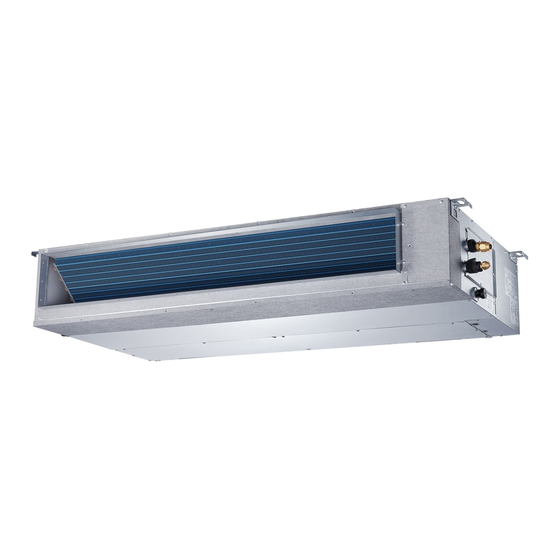
Ducted style ductless system
sizes 09 to 58
Hide thumbs
Also See for 40MBDQ series:
- Installation instructions manual (30 pages) ,
- Owner's manua (12 pages) ,
- Installation instructions manual (26 pages)
Table of Contents
Advertisement
40MBDQ
Ducted Style Ductless System
Sizes 09 to 58
A NOTE ABOUT SAFETY
GENERAL
. . . . . . . . . . . . . . . . . . . . . . . . . . . . . . . . . . . . . . . . . . . . . . . . . . . . . . . . . . . . . . . . . . . . . . . . . . . . . . . . . . . . . . . . . . . . . . . . .
PARTS LIST
. . . . . . . . . . . . . . . . . . . . . . . . . . . . . . . . . . . . . . . . . . . . . . . . . . . . . . . . . . . . . . . . . . . . . . . . . . . . . . . . . . . . . . . . . . . . . . . .
DISPLAY PANELS (SHIPPED INSIDE THE CONTROL BOX)
FUNCTION BUTTONS
. . . . . . . . . . . . . . . . . . . . . . . . . . . . . . . . . . . . . . . . . . . . . . . . . . . . . . . . . . . . . . . . . . . . . . . . . . . . . . . . . . . . . . .
REMOTE CONTROLLER
. . . . . . . . . . . . . . . . . . . . . . . . . . . . . . . . . . . . . . . . . . . . . . . . . . . . . . . . . . . . . . . . . . . . . . . . . . . . . . . . . . . .
REMOTE CONTROL FUNCTIONS
CLEANING, MAINTENANCE AND TROUBLESHOOTING
Please read this Owner's Information Manual carefully before installing and using this appliance
and keep this manual for future reference.
For your convenience, please record the model and serial numbers of your new equipment in the
spaces provided. This information, along with the installation data and dealer contact information,
will be helpful should your system require maintenance or service.
UNIT INFORMATION
Model # ___________________________________
Serial # ___________________________________
INSTALLATION INFORMATION
Date Installed _____________________________
Owner's Manual
TABLE OF CONTENTS
. . . . . . . . . . . . . . . . . . . . . . . . . . . . . . . . . . . . . . . . . . . . . . . . . . . . . . . . . . . . . . . . . . . . . . . . . . . . . . . . . . .
. . . . . . . . . . . . . . . . . . . . . . . . . . . . . . . . . . . . . . . . . . . . . . . . . . . . . . . . . . . . . . . . . . . . . . . . . . . . .
NOTE TO EQUIPMENT OWNER:
. . . . . . . . . . . . . . . . . . . . . . . . . . . . . . . . . . . . . . . . . . . . . . . . . . . . . . .
. . . . . . . . . . . . . . . . . . . . . . . . . . . . . . . . . . . . . . . . . . . . . . . . . . . .
DEALERSHIP CONTACT INFORMATION
Company Name: _________________________________
Address:_________________________________________
________________________________________________
Phone Number:__________________________________
Technician Name:_________________________________
________________________________________________
PAGE
2
2
3
3
4
5
7
9 − 11
Advertisement
Table of Contents

Related Manuals for Carrier 40MBDQ series


Summary of Contents for Carrier 40MBDQ series
- Page 1 40MBDQ Ducted Style Ductless System Sizes 09 to 58 Owner’s Manual TABLE OF CONTENTS PAGE A NOTE ABOUT SAFETY ................. . . GENERAL .
-
Page 2: Operating Modes
A NOTE ABOUT SAFETY GENERAL The ducted fan coil unit provides quiet, maximum comfort. In Any time you see this symbol in manuals, instructions and on addition to cooling and/or heating, the ducted fan coil unit the unit, be aware of the potential for personal injury. There are matched with an outdoor condensing unit filters and three levels of precaution: dehumidifies the air in the room to provide maximum comfort. -
Page 3: Parts List
PARTS LIST Table 1—Parts List PART NAME INDOOR UNIT DRAIN ADAPTER AIR FILTER WIRED CONTROLLER WIRELESS REMOTE Air inlet Electric control cabinet Air filter Drain hose(field supplied) Air outlet Refrigerant connecting pipe (field supplied) Fig. 1 − Parts List NOTE: Images are for illustration purposes only. DISPLAY PANELS (SHIPPED INSIDE THE CONTROL BOX) Manual button LED display... -
Page 4: Function Buttons
FUNCTION BUTTONS Before you begin using your new air conditioner, make sure to familiarize yourself with the remote control. The following is a brief introduction to the remote control. ON/OFF Activate/Disable freeze Turns the unit on or off protection function. MODE TEMP Scrolls through operation... -
Page 5: Remote Controller
REMOTE CONTROLLER Fig. 4 − Remote Controller Remote Controller Display Transmission Indicator Lights up when the remote sends a signal to indoor unit ON/OFF display MODE display Appears when the unit is turned on, Displays the current and disappears when it is turned off mode, including: TIMER OFF display TIMER ON display... -
Page 6: Manual Operation
Remote Control Operation − Quick Start CAUTION NOTE: When transmitting a command from the remote control to the unit, be sure to point the control toward the right side of the EQUIPMENT DAMAGE HAZARD unit. The unit confirms receipt of a command by sounding an Failure to follow this caution may result in equipment audible beep. -
Page 7: Remote Control Functions
REMOTE CONTROL FUNCTIONS DIRECT Pressing On/Off NOTE: The DIRECT feature is not available on this model. When the air conditioner is not in operation, the remote control SWING displays the last set point and mode. NOTE: The SWING feature is not available on this model. S Press ON/OFF to start the unit. -
Page 8: Turbo Mode
Sleep Mode Freeze Protection Mode SLEEP mode is used to conserve energy and can be used when Press FP for approximately 2 seconds to activate or deactivate the unit is in the COOL, HEAT or AUTO mode only. the freeze protection mode (heating set back). The indoor unit Cool Mode displays “FP”. -
Page 9: Periodic Maintenance
CLEANING, MAINTENANCE AND TROUBLESHOOTING 3. Vacuum filters. CAUTION ELECTRICAL SHOCK HAZARD Failure to follow this caution may result in personal injury or death. Always turn off power to the system before performing any cleaning or maintenance to the system. Turn off the outdoor disconnect switch located near outdoor unit. -
Page 10: Troubleshooting
Energy Saving Recommendations S Use drapes, curtains or shades to keep direct sunlight from The following recommendations will add greater efficiency to the ductless system: heating the room on very hot days. S Limit the unit’s run time by using the TIMER function. S Select a comfortable thermostat setting and leave it at chosen S Do not obstruct the air intake on the front panel. -
Page 11: Common Problems
Common Problems The following symptoms are not malfunctions and in most situations will not require repairs. Table 3—Common Problems Problem Possible Causes The unit has a 3-minute protection feature that prevents the unit from overloading. The unit cannot be restarted within three minutes of being turned off. Cooling and Heating Models: If the Operation light and PRE-DEF (Pre-heating/ Defrost) indicators Unit does not turn on when pressing ON/ OFF are lit up, the outdoor temperature is too cold and the unit’s anti-cold wind is activated in order to... - Page 12 Copyright 2018 CAC/BDP S 7310 W. Morris St. S Indianapolis, IN 46231 Edition Date: 03/18 Catalog No: OG-40MBDQ-03 Replaces:OG-40MBDQ-02 Manufacturer reserves the right to change, at any time, specifications and designs without notice and without obligations.