Advertisement
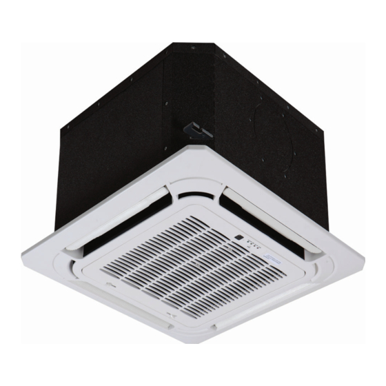
40MBCQ
Cassette Ductless System
Sizes 09 to 48
NOTE: The images in this manual are for illustration purposes
only. The actual model may differ slightly.
NOTE: Read the entire instruction manual before starting the
installation.
Installation Instructions
TABLE OF CONTENTS
. . . . . . . . . . . . . . . . . . . . . . . . . . . . . . . . . . . . . . .
. . . . . . . . . . . . . . . . . . . . . . . . . . . . . . . . . . . . . . . . . . .
. . . . . . . . . . . . . . . . . . . . . . . . . . . . . . . . . . . . . .
. . . . . . . . . . . . . . . . . . . . . . . . . . . . . . . . . . . . .
. . . . . . . . . . . . . . . . . . . . . . . . . . . . . . . .
. . . . . . . . . . . . . . . . . . . . . . . . . . . . . . .
. . . . . . . . . . . . . . . . . . . . . . . . . . . . . . . . . . . . . . . .
. . . . . . . . . . . . . . . . . . . . . . . . . . . . . .
. . . . . . . . . . . . . . . . . . . . . . . . .
. . . . . . . . . . . . . . . . . . . . . . . . . . .
. . . . . . . . . . . . . . . . . . . . . . .
. . . . . . . . . . . . . . . . . . . . . . . . .
PAGE
2
3
4
4
5
7
8
8
14
15
16
17
Advertisement
Table of Contents

Related Manuals for Carrier 40MBCQ


Summary of Contents for Carrier 40MBCQ
-
Page 1: Table Of Contents
40MBCQ Cassette Ductless System Sizes 09 to 48 Installation Instructions TABLE OF CONTENTS PAGE SAFETY CONSIDERATIONS ...... -
Page 2: Safety Considerations
SAFETY CONSIDERATIONS WARNING Installing, starting up, and servicing air−conditioning equipment can be hazardous due to system pressures, electrical components, ELECTRICAL SHOCK HAZARD and equipment location (roofs, elevated structures, etc.). Failure to follow this warning could result in personal Only trained, qualified installers and service mechanics should injury or death. -
Page 3: Parts List
PARTS LIST Table 1—Parts List PART NO. PART NAME Air flow louver (at air outlet) Drain pump (drain water from the indoor unit) Drain pipe (Field Supplied) Air outlet Air filter (inside grille/ceiling panel) Air inlet Grille/Ceiling panel (Required - sold separately) Display panel Remote controller Refrigerant pipe (Field Supplied) -
Page 4: System Requirements
SYSTEM REQUIREMENTS Allow sufficient space for airflow and unit servicing. See Fig. 4 for the minimum required distances between the unit and the walls or ceilings. PIPING IMPORTANT: Both refrigerant lines must be insulated separately. S Minimum refrigerant line length between the indoor and outdoor units is 10 ft. (3 m). S Table 3 lists the pipe sizes for the indoor unit. -
Page 5: Dimensions
DIMENSIONS Table 4—Dimensions Indoor UNIT SIZE Body Panel Body Panel Body Panel Body Panel Body Panel Body Panel DIMENSIONS 10.24 1.97 10.24 1.97 10.24 1.97 8.07 2.17 9.65 2.17 11.3 2.17 Height (mm) (260) (50) (260) (50) (260) (50) (205) (55) (245) (55) - Page 6 DIMENSIONS (CONT) 3.62(92) 75 Fresh air intake 3.15(80) 5.35(136) 4.96(126) 4-install hanger 3.58(91) 26.77(680) Body Gas side 3.54(90) 5.31(135) Liquid side Wiring connection port E-parts box Service hole for Test mouth & Test cover draining pump 32 Drain hole 5.20(132) 26.77(680) 7.72(196) 33.07(840)
-
Page 7: Clearances
CLEARANCES Fig. 4 - Cassette Unit Clearance... -
Page 8: Installation Tips
INSTALLATION TIPS Indoor Unit Installation locations include: S A location where no obstacles exist near the inlet and outlet areas. S A location which can bear the indoor unit’s weight is critical. S Do not install the indoor units near a direct source of heat such as direct sunlight or a heating appliance. - Page 9 NOTE: For a non−standard installation, contact your dealer for details. When installing optional accessories, review the optional accessories list in the installation manual. Depending on field conditions, it may be easier to install optional accessories before the indoor unit is installed (except for the decoration panel).
- Page 10 DRAIN PIPING WORK Drain Piping Installation 1~1.5m Install the drain piping (see Fig. 13) and take steps to eliminate 300/11.8in 3~5ft condensation. Improperly rigged piping could lead to leaks and eventually wet furniture and belongings. 1-1.5m 3~5ft Fig. 13 - Drain Piping Installation Unit: mm Fig.
- Page 11 DRAIN PIPE TESTING 1. Plastic watering can (tube) should be about 3.9 in. (100 mm). After the piping work is finished, check if the drainage flows smoothly. 2. Water receiver. Add approximately 1 liter of water gradually through the air Electrical Wiring discharge outlet.
- Page 12 INSTALLATION OF THE DECORATION PANEL Detach the intake grill 1. Slide the two grille hooks toward the middle of the decoration panel. Decoration panel Screws (M5)(supplied with the panel) Intake grille Fig. 24 - Attach the Decoration Panel Grille hook Fig.
- Page 13 Fig. 27 - Connect the two louver connectors Fig. 28 - Connect display panel connectors Grille Louver Motor Power. Grille Display 5 Pin Port 10 Pin Port CN40 Connector Used for Wired Remote Control with a 4 Pin Molex plug Wired Remote Controller Grille Display.
-
Page 14: Electrical Data
6. Fasten the control box lid with two screws. Fig. 33 - Adjust Height of Indoor Unit Fig. 30 - Fasten the Control Box Lid Fig. 34 - Adjust Height of Indoor Unit CAUTION Fig. 31 - Fasten Installation Covers UNIT DAMAGE HAZARD 7. -
Page 15: Connection Diagrams
CONNECTION DIAGRAMS Fig. 35 - Connection Diagrams (Sizes 9−24) Fig. 36 - Connection Diagrams (Sizes 36−48) Notes: 1. Do not use the thermostat wire for any connection between indoor and outdoor units. 2. All connections between the indoor and outdoor units must be as shown. The connections are sensitive to polarity and will result in a fault code. Fig. -
Page 16: Start−Up
EVACUATE BREAK VACUUM WITH DRY NITROGEN WAIT Indoor unit tubing Flare nut Piping EVACUATE Fig. 40 - Align Pipe Center BREAK VACUUM WITH DRY NITROGEN h. Connect both the liquid and gas piping to the indoor unit. i. Tighten the flare nut using a torque wrench as specified in WAIT Table 7. -
Page 17: Troubleshooting
TROUBLESHOOTING For ease of service, the systems are equipped with diagnostic code The indoor diagnostic display is a combination of flashing LEDs display LEDs on both the indoor and outdoor units. The outdoor on the display panel or the front of the unit. If possible, always diagnostic display consists of two LEDs (Red and Green) on the check the diagnostic codes displayed on the indoor unit first. - Page 18 Catalog No: IM-40MBCQ-03 Copyright 2018 CAC / BDP D 7310 W. Morris St. D Indianapolis, IN 46231 Edition Date: 10/18 Manufacturer reserves the right to change, at any time, specifications and designs without notice and without obligations. Replaces:IM-40MBCQ-02...