Table of Contents
Advertisement
Quick Links
DATA PROJECTOR
MODEL
XD70U
User Manual
* DLP™ (Digital Light Processing) and DMD (Digital Micromirror Device) are registered trademarks of Texas Instru-
ments Incorporated (U.S.A.).
* DMD is an ultra-precise part developed by Texas Instruments (U.S.A.) which takes the place of liquid crystal (in the
projector).
* VGA and XGA are trademarks or registered trademarks of International Business Machines Corporation (U.S.A.).
* S-VGA is a registered trademark of Video Electronics Standards Association.
* Microsoft, Windows, and PowerPoint are registered trademarks of Microsoft Corporation (U.S.A. and other countries).
* Macintosh is a trademark of Apple Computer Inc. (U.S.A.).
* TMDS is a trademark of Silicon Image, Inc.
Note that even in the absence of explanatory notes, serious attention is paid to the trademarks of the various companies
and to the product trademarks.
XD70
IMPORTANT
Advertisement
Chapters
Table of Contents

Related Manuals for Mitsubishi DATA PROJECTOR


Summary of Contents for Mitsubishi DATA PROJECTOR
-
Page 1: User Manual
DATA PROJECTOR MODEL XD70U User Manual * DLP™ (Digital Light Processing) and DMD (Digital Micromirror Device) are registered trademarks of Texas Instru- ments Incorporated (U.S.A.). * DMD is an ultra-precise part developed by Texas Instruments (U.S.A.) which takes the place of liquid crystal (in the projector). -
Page 2: Important Safety Information
SION CORD, RECEPTACLE OR OTHER OUTLET UNLESS THE BLADES CAN BE FULLY IN- SERTED TO PREVENT BLADE EXPOSURE. NOTE: SINCE THIS PROJECTOR IS PLUGGABLE EQUIPMENT, THE SOCKET-OUTLET SHALL BE IN- STALLED NEAR THE EQUIPMENT AND SHALL BE EASILY ACCESSIBLE. WARNING Use the attached specified power supply cord. - Page 3 IMPORTANT SAFETY INFORMATION CAUTION Do not look at the laser pointer’s light source. Be sure to heed the following. Pointing the laser beam at This label is located on the side of the remote control. the eyes could lead to reduced vision or vision impairment. •...
- Page 4 (d) If the projector has been exposed to rain or wa- ter. (e) If the projector has been dropped or the cabinet has been damaged.
- Page 5 The heated Air outlet grille and Bottom plate may cause injury or damage to other equipment. Also, do not set the projector on the desk which is easily af- fected by heat. Do not look into the air outlet grille when projector is operating.
-
Page 6: Major Features
Powerful functions for presentations A wide variety of easy-to-set functions have been built into the projector, from a digital keystone correction function (used when making settings) that corrects picture distortion, to an auto adjustment function that automatically identifies the PC signal. -
Page 7: Table Of Contents
Connecting Personal Computers and Video Equipment ... E-16 Connections with Personal Computer ... E-16 Connect the projector’s RGB connector using the included RGB signal cable. .. E-16 To Output the External Output Signal of a Notebook Computer ... E-17 Connections with Composite Signals ... E-18 Video Equipment with VIDEO Connectors ... -
Page 8: Table Of Contents
Table of Contents Color ... E-46 Quick Color Adj..E-46 Gamma ... E-46 Color Temp..E-47 White ... E-47 Color Space ... E-47 White Balance ... E-48 View ... E-49 Aspect ... E-49 Filter ... E-49 Vertical Flip/Horizontal Flip ... E-50 Keystone ... -
Page 9: Checking The Supplied Accessories
Connections are described on Page E-20. No. 777918400 USB cable (type A, 2 m / 6.6 feet) [1] Used to perform mouse operations on a computer using the projector’s remote control unit. Connections are described on Page E-32. No. 777918600... - Page 10 HOW TO PUT THE PROJECTOR INTO THE STORAGE CASE Close the lens shutter or lens cap before putting the pro- jector in its case, then fasten the projector in place with the Velcro belt. Place the accessories in the storage pocket.
-
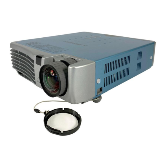
Page 11: Names Of The Main Unit Parts
Names of the Main Unit Parts Zoom ring [E-24] Focus ring [E-25] Exhaust vents Remote control sensor [E-13] Lens Lens cap Remove before use. Attach the lens cap after use to protect the lens. Ventilation slots Adjusters [E-25] E-10 Ventilation slots Adjuster button [E-25] (Also on opposite side) Lamp cover [E-62]... - Page 12 Names of the Main Unit Parts STATUS indicator [E-21, 58] STANDBY indicator [E-21, 58] STANDBY button [E-21] AUTO button [E-26] SOURCE button [E-26] Remote control sensor [E-13] AC IN connector [E-21] MOUSE connector [E-32] AUDIO connector [E-20] S VIDEO S-VIDEO connector [E-18] RGB connector [E-16, 19] Built-in Security Slot This security slot supports the MicroSaver Security System manufactured by...
-
Page 13: Names Of The Remote Control Parts/Preparing The Remote Control
Names of the Remote Control Parts/Preparing the Remote Control STANDBY button [E-21, 23] This button is used to switch ON the power and set the unit to the STANDBY mode. Buttons used for input selection [E-26] RGB button and VIDEO button (VIDEO / S-VIDEO) Buttons used for menu operations [E-37]... -
Page 14: Remote Control Range
Names of the Remote Control Parts/Preparing the Remote Control Remote Control Range Point the infrared transmitter of the remote control toward the remote control sensor located at the front or rear of the main unit and operate. Reception of the remote control signal should generally be possible within the range illustrated below. Side View 30°... -
Page 15: The Procedure Up To Projecting To The Screen
When making connections with the video equipment’s YCbCr connector or YPbPr connector, see “Connections with Component Signals” on Page E-19. When playing the audio through the built-in speaker of the projector, see “Connections with the AUDIO Jack” on Page E-20. -
Page 16: Placement Guide
Placement Guide • Use this information as a guide to find out about the screen size when the projector is placed at a certain location, or to find out the approximate size of a screen that will be required. • When suspending the projector from the ceiling, change the projection method. See “Vertical Flip” on E-50. -
Page 17: Connecting Personal Computers And Video Equipment
• The projector has been set to “Auto” at the factory; however, if it does not project, please change the input setting to “RGB” using the menu sequence of [Setup] → [Input Format] → [RGB]. See “Input Format” on Page E-53. -
Page 18: To Output The External Output Signal Of A Notebook Computer
Note: * When the liquid crystal display of the notebook computer and the projector are displayed at the same time, the projected image might not be correct even though the liquid crystal display shows a correct indication. Should this occur, stop the simultaneous display of the notebook computer and try the mode with external output only. -
Page 19: Connections With Composite Signals
Video Equipment with VIDEO Connectors • The input setting of the VIDEO connector has been set to “Auto” at the factory; however, if the projector does not project, please change the input setting to “Your Country’s Television Broadcast System” using the menu sequence of [Setup] → [Input Format] →... -
Page 20: Connections With Component Signals
When the Video Equipment Has a YCbCr Connector or YPbPr Connector • The projector has been set to “Auto” at the factory; however, if it does not project, please change the input setting to “Compo- nent” using the menu sequence of [Setup] → [Input Format] → [RGB]. -
Page 21: Connections With The Audio Jack
Connections with the AUDIO Jack * Make the connection to the projector’s AUDIO jack using the supplied audio cable. When the audio jack of the equipment that is to be connected is of the RCA phono type, make connection via the supplied audio conversion cable. -
Page 22: Power Cable Connections And Switching The Power On/Off
Switch on the power of the connected equipment Note: • When the power plug will be unplugged from the power outlet, please place the projector near the power outlet so that it may be reached easily. • Press the STANDBY button after the STANDBY indicator is lit in amber. - Page 23 The first time the power is switched on after purchase, [Menu Lan- guage Select] will be displayed. Follow the procedure described be- low and select the display language of the projector. If the image is blurred, turn the focus ring counterclockwise or clock- wise to focus it.
-
Page 24: Finishing
STANDBY The [Power Off] display appears. When the level gauge reaches maximum, the projection screen will go off (in about 5 seconds) and the projector will enter the power-off operation. Note * The operation can be cancelled by pressing a button other than the STANDBY button. -
Page 25: Adjustment Of The Projection Screen
Adjustment of the Projection Screen Turn the zoom ring to adjust the screen size of the projection image. Adjust the image to match the desired screen size. When outside of the adjustment range, move the projector to the rear or forward. -
Page 26: Making Adjustments With The Adjusters
Adjust so that there is no shaking of the projector. Note: When the projector has a suspended or rear installation is used, the orientation of the projection will need to be changed. Please see “Vertical Flip” on Page E-50. Focus ring... -
Page 27: General Operation
Note: * When you do not operate source selection, the projector will assume the input selec- tion condition that was previously used. * See “Auto Source” on Page E-51 for information about the Auto Source on and off conditions. -
Page 28: Selection Of Aspect Ratio
16:9 screen Note: When selection has been made for the “Real” setting of the personal computer signal (i.e., when the input signal and the projector display resolution are high) and the “Zoom” setting of the video signal, pressing the SELECT movement of the display position. -
Page 29: Freezing A Moving Picture
10 seconds. Note: * Adjustment of the volume will not produce any sound unless an image is being projected. * Please make connections to the AUDIO connectors of the projector with the supplied audio cable. button decreases the E-28 STANDBY... -
Page 30: Enlargement Of The Image And Video Movement
The image can also be moved in the following circumstances. • When “Aspect” is set to “Real” by the signal of the personal computer, and the input resolution is higher than the display resolution of the projector. • When “Aspect” is set to “Zoom” by the video signal. -
Page 31: Using The Presentation Timer
General Operation Using the Presentation Timer The presentation is given while checking the timer displayed on the screen. The gauge display allows the remaining time to be known at a glance. (1) Press the TIMER button to show the settings display. The display will close when an operation has not been made for about 10 seconds. -
Page 32: Using The Laser Pointer
General Operation Using the Laser Pointer The remote control unit’s laser pointer can be used to point to the section currently being explained, making presenta- tions more effective. CAUTION Do not look at the laser pointer’s light source. Be sure to heed the following. Pointing the laser beam at the eyes could lead to reduced vision or vision impairment. -
Page 33: Performing Mouse Operations On The Computer With The Remote Control Unit
5 seconds before reconnecting. Do not repeatedly disconnect and reconnect the cable in a momentary fashion. The personal computer may not be able to correctly identify the projector as a result. * The supplied USB cable is a dedicated cable for this projector. There is no guaranty that it will work in connections with other USB equipment. -
Page 34: Controlling The Projector From A Computer
Note: * This function may not work with some computers. * Specialized knowledge is required to use the control connector. Consult a specialist, such as the person suspending the projector from the ceiling. Serial cable (D-Sub 9-pin, straight) (commercially available) -
Page 35: Protecting The Projector With The Security Lock
General Operation Protecting the Projector with the Security Lock A password can be registered and the security lock set in order to protect the projector from unauthorized use. Registering the password The password is registered using the menus. For instructions on operating the menus, see “Menu Operations” on E-37. - Page 36 When a password has been registered, the “Password” input window appears on the projected image when the power is turned on. The projector continues projecting this image until the correct password is input. At this time, only the STANDBY button (power off) works.
-
Page 37: Using The Quick Menu
General Operation Using the Quick Menu This function permits frequently used adjustments to be performed quickly. Note that the Quick Menu will not be displayed unless the signal of the connected equipment is input. Please select the input that you wish to adjust. (1) A press of the QUICK MENU button brings up the quick adjustment display. -
Page 38: Menu Operation Method
• Adjustments and settings are made by projecting an image and adjusting to an optimum condition. • The remote control should be pointed toward the remote control sensor of the projector and operated. • To return the various items that have been changed via the menu to their standard values (i.e., default values at time of shipping from the factory), see “Factory Default”... - Page 39 Menu Operation Method Menu Screen Names and Functions Menu Name This is the title of the menu. There is a change to the title screen when the menu is selected. The cursor moves to the selected menu name. Item Name This is the name of the ad- justment or setting.
- Page 40 Preparation Switch on the power of the connected equipment, start the play operation or another operation, and input the signal to the projector. Select the input that you wish to adjust. The menu display of the description diagram depicts an example in which the “Keystone” item name is selected.
- Page 41 Menu Operation Method Displaying the Cursor Press the SELECT button to display the item name selection cursor. STANDBY LASER VIDEO AUTO MENU QUICK R-CLICK/ ENTER CANCEL TIMER FREEZE MUTE Selection of the Item Name Press the SELECT STANDBY LASER VIDEO AUTO MENU QUICK...
- Page 42 Menu Operation Method Closing the Menu Press the MENU button and close the menu display STANDBY LASER VIDEO AUTO QUICK MENU R-CLICK/ ENTER CANCEL FREEZE MUTE TIMER Selecting Another Menu Name with Remote Control Operation When a sub menu is displayed, press the CANCEL but- ton and close the sub menu.
-
Page 43: List Of Item Names Offering Input Selection And Adjustments/Settings
Menu Operation Method List of Item Names Offering Input Selection and Adjustments/Settings The item names that can be adjusted/set will differ depending on the input signal. [Example of Menu Display Items at the Time of Input Signal RGB Selection] Menu name Item Name Image Brightness... -
Page 44: Menu Name
Menu Operation Method Menu name Item Name Setup Auto Source Auto Power Off Memu Position Lamp Mode Input Format Presentation Timer Option Language On Screen Background Startup Screen Security Lock Info. Status Factory Default Lamp Timer Reset Resolution Frequency Lamp Timer Sub Menu Item Name Video... -
Page 45: Image
Image • Perform this operation while projecting the picture for which the adjustment/setting will be made. • Select the menu name “Image”. See “Menu Operation Method” on Page E-37 for information about performing menu operations. The item name display will differ depending on the input signal. -
Page 46: Reset
Image Fine Picture Adjust this when the picture shows a lack of color fidelity or flickering. Select the “Fine Picture” item name and adjust with the SELECT so that the lack of color fidelity or the flickering disappears. H Position Adjust this when the picture is shifted to the left or right. -
Page 47: Color
Color • Do the following operation while displaying the image you want to adjust or set. • Select the menu name “Color”. See “Menu Operation Method” on Page E-37 for information about performing menu operations. The item name display will differ depending on the input signal. -
Page 48: Color Temp
Note: * When the component signal undergoes conversion processing to red, green, and blue which express the image of the projector, the correct color cannot be reproduced unless a system compliant with the color difference conversion sys- tem of the input signal is used. Color Space serves to make this selection. -
Page 49: White Balance
Color White Balance This function automatically adjusts the black level and the white level of the analog RGB input signal to suit the personal computer. Select the item name [White Balance] and press the ENTER button. The display will change to [Input Black Signal]. The screen background color of the connected personal computer will be set to black. -
Page 50: View
Filter This function sets the sharpness when the input signal is adjusted to the resolution of the projector and enlarged or reduced. Select the item name “Filter” and select the setting contents with the SELECT buttons. -
Page 51: Vertical Flip/Horizontal Flip
Vertical Flip/Horizontal Flip In selecting the method of projecting to the screen, these functions are set when the projector is in a suspended or a rear screen installation. Select the item name “Vertical Flip” or “Horizontal Flip” and select the setting contents with the SELECT buttons. -
Page 52: Setup
Note: Some video decks and other equipment output a blue background or other video when playback ends. When this happens, a signal is being input to the projector and Auto Power Off is not activated. E-51... -
Page 53: Menu Position
Setup Menu Position This function sets the display position of the menu. Select item name “Menu Position” and select the setting contents with the SELECT buttons..Displays on the left side ... Displays on the right side Lamp Mode Use this if the picture is projected on a small screen and the picture is too bright or when projecting images in dark rooms. -
Page 54: Input Format
Setup Input Format This function is used in setting the input signals of the input connec- tors. Normally, this should be set to Auto. When identification is not possible with Auto, make the setting. Select the item name “Input Format”, press the ENTER button, and the sub menu will open. -
Page 55: Option
Option • Select menu name “Option”. See “Menu Operation Method” on Page E-37 for information about performing menu operations. The item name display will differ depending on the input signal. See “List of Item Names Offering Input Selection and Adjustments/Settings” on Page E-42. Language This function sets the language that is displayed on screen in the messages and menu displays. -
Page 56: Startup Screen
Logo ... Displays the logo. Blank ... Does not display the logo. Note: When “Logo” is selected at the startup screen, the “PROJECTOR XD70” logo is displayed. Security Lock A password can be registered and the security lock set in order to prevent unauthorized use of the projector. -
Page 57: Info
There is a change to the status display. Press the CANCEL button to return to the menu. Display Contents: Projector model and firmware version. Factory Default This function returns the adjustments and settings of all the in- put sources to the standard factory default values. -
Page 58: Resolution / Frequency
This function displays the resolution and frequency of the detected in- put signal. Lamp Timer This displays the lamp timer. This projector has an Low mode function. The lamp life will differ between Normal mode and Low mode. Lamp Life Use only in Normal mode: approx.2000 hours Use only in Low mode: approx.3000 hours... -
Page 59: When An Indicator Is Lit Or Flashing
2. Check the following matters and take the required measures. When the projector is being used in a location that has a high ambient temperature, set it up again in a cool location. Check the outflow and intake holes and clean them if they are obstructed. -
Page 60: Troubleshooting
• Does the projection distance exceed the focusing range? • Is there condensation on the lens, etc.? If the projector is moved from a cool storage area to a warm place and the power is turned on, condensation may form on the lens or internal optical parts. -
Page 61: Cleaning
Cleaning the Inside of the Projector Cleaning of the inside of the projector is required about once a year. Failure to clean over a long period while dust has collected inside the projector could cause a fire or breakdown. Do not clean the inside of the projector by yourself. Please be sure to contact your dealer. -
Page 62: Replacing The Lamp Cartridge
Replacing the Lamp Cartridge • The lamp that is used as a light source in the projector has a limited service life. The rated service life of the lamp is about 2000 hours (when used in normal mode only). This could be shortened depending on conditions of use and other factors. - Page 63 Replacing the Lamp Cartridge Preparations: Turning the projector upside-down on top of a soft cloth, etc., so that it does not get scratched makes it easier to replace the lamp cartridge. Turn the projector right-side up after replacing the lamp cartridge.
- Page 64 After reaching the lamp service life, if the lamp is used for more than another 100 hours, it will not be possible to switch on the power. Should this happen, while the projector is in the standby mode, simultaneously holding down the projector’s SOURCE button and AUTO button for more than 5 seconds will clear the lamp timer.
-
Page 65: Specifications
8.5 in.(W) 2.4 in.(H) 10.3 in.(D) (not including protrusion) Weight Approximately 2.0 kg / 4.4 lbs Operational Temperatures Data projector: 5° to 35°C (41° to 95°F), 30 to 85% humidity • Specifications and design are subject to change without notice. E-64... -
Page 66: Table Of Supported Frequency
Table of Supported Frequency The projector automatically identifies the signal input from the computer and selects the optimum resolution as shown on the table below. Manual adjustments may be required for some input signals. See “Picture Adj. / Fine Picture / H Position / V Position” on page E- 44, 45. -
Page 67: Cabinet Dimensions
Cabinet Dimensions SOURCE AUTO STANDBY STANDBY STATUS 216 (8.5) Unit: mm (inch) E-66... - Page 68 MITSUBISHI ELECTRIC CORPORATION 1 Zusho Baba, Nagaokakyo-City, Kyoto Japan...