Invacare Leo User Manual
Hide thumbs
Also See for Leo:
- User manual (88 pages) ,
- Operating manual (67 pages) ,
- Service manual (44 pages)

Related Manuals for Invacare Leo


Summary of Contents for Invacare Leo
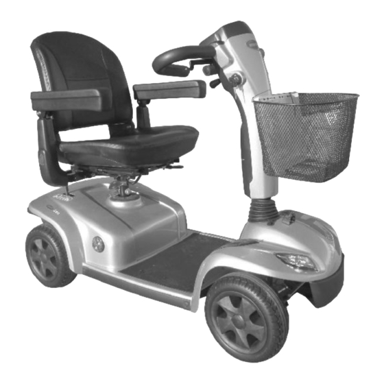
- Page 1 Invacare® Leo en Scooter User Manual This manual MUST be given to the user of the product. BEFORE using this product, read this manual and save for future reference.
- Page 2 All rights reserved. Republication, duplication or modification in whole or in part is prohibited without prior written permission from Invacare. Trademarks are identified by ™ and ®. All trademarks are owned by or licensed to Invacare Corporation or its subsidiaries unless otherwise noted.
-
Page 3: Table Of Contents
5 Setup ......... . 19 Contents 5.1 Adjusting the Armrest Width . - Page 4 7.2.6 Instructions on using the batteries ....30 11.1.1 Error diagnosis ......44 7.2.7 Transporting batteries.
-
Page 5: General
If you find that the font size in the print version of the user manual Indicates a hazardous situation that could result in is difficult to read, you can download it as a pdf from the Invacare damage to property if it is not avoided. -
Page 6: Intended Use
Invacare® Leo compact and agile enough for indoor areas, but also able to overcome many obstacles in outdoor areas. 1.4 Intended use This vehicle was designed for persons whose ability to walk is impaired, but who are still in terms of their eyesight and physically and mentally able to operate an electric vehicle. -
Page 7: Safety
Safety 2 Safety WARNING! Risk of injury if the power is switched off while the scooter is in motion, due to it coming to an 2.1 General safety notes abrupt, sharp stop – If you have to brake in an emergency, simply release WARNING! the drive lever and allow the scooter to come to a Risk of injury if mobility device is used in any... -
Page 8: Safety Information On Electromagnetic Interference
– Do not exceed the maximum permissible load (refer – Only use original Invacare spare parts, which have to 12 Technical data, page 47). been approved for use with this mobility device. – The mobility device is only designed for use by a single... -
Page 9: Safety Information On Driving And Freewheel Mode
Safety 2.3 Safety information on driving and freewheel WARNING! mode Risk of malfunction due to electromagnetic interference WARNING! – Do not switch on or operate portable transceivers or Risk of injury if the mobility device tips over communication devices (such as radio transceivers or –... - Page 10 Invacare® Leo WARNING! Risk of injury if the mobility device tips over (continued) – Never use the mobility device to transport more than one person. – Do not exceed the maximum permissible load. – When loading the mobility device, always distribute the weight evenly.
-
Page 11: Safety Information With Regard To Care And Maintenance
– DO NOT attempt to carry out maintenance work that is not described in this user manual. Such repair and/or service MUST be performed by a qualified technician. Contact a dealer or Invacare technician. Identification label sticker on CAUTION! the seat post. - Page 12 Invacare® Leo Battery label under the cover at This product complies with Directive 93/42/EEC the rear concerning medical devices. The launch date of this product is stated in the CE declaration of conformity. Identification of the position of the coupling lever for driving The product needs to be tied down at indicated and push operation.
-
Page 13: Components
Components 3.2 Operating console arrangement 3 Components 3.1 Main parts of the scooter Battery charge display Speed controller Operating console Horn Lever for adjusting tiller inclination Left-hand direction indicator (switches itself off automatically Keyswitch (ON/OFF) after 30 seconds) Unlocking lever for swivelling and removing seat (left below Lighting seat) Status display... -
Page 14: Status Display
Invacare® Leo 3.2.1 Status Display The ON/OFF diode is used as a fault display (status display). It will flash if there is a problem with the scooter. The number of flashes indicates the type of error. Refer to 11.1.2 Error codes and diagnostic codes, page 44. -
Page 15: Accessories
You can find in the correct sitting position. more information about maintenance work on belts in the service manual, which is available from Invacare. 4.1.1 Types of postural belts Your mobility device can be fitted with the following postural belt 4.1.3 Installing the Seat Positioning Strap... -
Page 16: Rollator Bracket
4.2 Rollator bracket Your scooter can be fitted with an optional rollator bracket. Only the following rollators, which have been approved by Invacare, can be transported using this bracket: • Dolomite Jazz 600 •... -
Page 17: Removing The Rollator Bracket
Accessories 4.2.2 Removing the rollator bracket Dolomite Legacy 600 Invacare Banjo P452E/3 Loosen the screws (1). Pull the rollator bracket out of the fixtures. 4.2.3 Positioning the rear reflector CAUTION! Risk of accident due to poor visibility If you wish to use your wheelchair on public roads and a rear reflector is required by national legislation, then the rollator bracket may not cover the rear reflector. - Page 18 Invacare® Leo Position the rear reflector as shown in the drawing. 1506942-P...
-
Page 19: Setup
Setup 5 Setup 5.1 Adjusting the Armrest Width WARNING! – Do not pull the armrest tube out of the seat frame beyond the STOP label on the armrest. Otherwise, Lift up the armrest. the armrest tube may fall out of the seat frame and Loosen the jam nut A. -
Page 20: Adjusting The Seat Position Forward/Rearward
Invacare® Leo 5.4 Adjusting the Seat Position Forward/Rearward Removing Pull up the seat lock lever A. The seat position lever is located on the right side of the seat. Turn the seat assembly B to one side. Hold the seat assembly firmly by the backrest and the front Pull the seat position lever A to disengage the seat B. -
Page 21: Adjusting The Tiller Angle
Setup 5.7 Adjusting the Tiller Angle Risk of damage – Use the seat swivel option with caution when WARNING! accessories are installed (such as safety flag, Risk of injury or damage crutch/cane holder, etc.). Otherwise, damage to the – Before performing any maintenance, adjustment or scooter or property may occur. -
Page 22: Adjusting Seat Height
Invacare® Leo Release the tiller adjustment lever to lock the tiller into the Install the remaining washer onto the mounting screw. desired position. Install the locknut and cap onto the mounting screw to secure Gently push/pull against tiller to ensure that the tiller is securely the seat post to the frame tube. - Page 23 Setup DO NOT hold the buttons for more than 5 seconds. If LED 7 blinks five times the audible signal has been successfully activated. The scooter will return to normal operating status automatically. Audible Signal AUDIBLE KEYSTROKE CONDI- SIGNAL COMBINATION LEDS TION Lighting C + Left...
-
Page 24: Usage
Invacare® Leo 6 Usage 6.1 Getting in and out Lift the detent lever A up. The armrests can be swivelled upwards to assist getting in and out. The seat can also be rotated to assist getting in and out. Turn the seat to the side. -
Page 25: Before Driving For The First Time
Usage 6.2 Before driving for the first time 6.3.3 The correct way to overcome obstacles Before you take your first trip, you should familiarize yourself well with the operation of the vehicle and with all operating elements. Take your time to test all functions and driving modes. If installed, make sure to properly adjust and use the postural belt each time you use the wheelchair. -
Page 26: Parking And Stationary
Invacare® Leo 6.7 Pushing the scooter by hand WARNING! Risk of tipping over CAUTION! – Only ever drive downhill at a maximum of 2/3 of the Risk of injury if someone sits on a scooter with top speed. disengaged motors –... -
Page 27: Driving The Scooter
Disengaging the drive The control system is programmed with standard values in Switch off the scooter (keyswitch). the works. Your Invacare dealer can carry out programming Press the unlocking knob on the disengaging lever (1). tailored to fit your requirements. -
Page 28: Electrical System
Try to provide a 24 hour charge once a week to make sure that A defective main fuse may be replaced only after checking both batteries are fully charged. the entire electric system. An Invacare specialised dealer • Do not cycle your batteries at a low state of charge without must perform the replacement. -
Page 29: How To Charge The Batteries
– Do not use the battery charger if it has been dropped be left unattended during charging. All charging devices which or damaged. are supplied by Invacare comply with these requirements. • You cannot overcharge the batteries when using the charger... -
Page 30: How To Disconnect The Batteries After Charging
Invacare® Leo 7.2.4 How to disconnect the batteries after charging • Pay attention to the Battery Charge Indicator! Charge the batteries when the Battery Charge Indicator shows that battery Disconnect the battery charger from the power supply. charge is low. -
Page 31: Transporting Batteries
Disposing of dead or damaged batteries correctly technologies, or use batteries that do not have similar date Dead or damaged batteries can be given back to your dealer or codes. directly to Invacare. • Never mix gel with AGM batteries. •... -
Page 32: Battery Charger
Invacare® Leo 7.3 5 A battery charger 7.3.3 LED display 7.3.1 Symbols found on the product Green flashes Waiting for connection to battery Orange flashes Pre-charge This product complies with Directive 93/42/EEC concerning medical devices. The launch date of this... -
Page 33: Operating Instructions
Electrical system • • Power Supply Cord: Use UL Listed detachable power supply If the green CHARGING LED keeps flashing, it cannot turn to cord-No. 18 AWG, 2 conductors, flexible cord, rated 10 A, indicate charging: VW - 1, 105 C, minimum 1.8 m , maximum 3 m long. Provided –... - Page 34 Invacare® Leo Input current 2.5 A max. (AC) Input voltage 100 - 240 V, 50/60 Hz (AC) Degree of AC-DC 80% efficiency Operating 0 °C – 40 °C temperature Switching Switch mode method Charging Constant current, two levels of constant voltage...
-
Page 35: Transport
Transport 8 Transport 8.1 Transport - General information WARNING! Risk of severe or fatal injuries in the event of a traffic accident if this mobility device is used as a vehicle seat! It does not fulfill the requirements of ISO 7176-19:2001. –... -
Page 36: Removing/Installing The Batteries
Invacare® Leo Ensure the release lever is locked and the front and rear frame Secure the batteries to the base frame using the battery retention assemblies are connected. strap A. Securely tighten. Connect the main wiring harness connector A. The battery retention strap should go under the battery Install the batteries. -
Page 37: Maintenance
Invacare dealer. A more comprehensive list of inspection checks and instructions for maintenance work can be found in the service manual for this device, which can be obtained from Invacare. That manual, however, is intended to be used by trained and authorized service technicians, and describes tasks which are not intended to be performed by the user. - Page 38 Invacare® Leo Weekly Monthly Inspection work (to be carried out by user) Before each journey Check for foreign bodies (glass splinters, nails) and damage. Replace tire if necessary. Front wheels: Front wheels must spin smoothly. If wheels wobble or do not spin easily, adjust steering pivot pin or front wheel bearing.
-
Page 39: Repair Instructions
For the specifications of spare parts please see 12 Technical data, page 47, or consult the service manual, available from Invacare (in this connection please see the addresses and phone numbers at the end of this user manual). In case you require assistance, please contact your Invacare dealer. -
Page 40: Removing/Installing The Front Wheel - Three Wheel Models
Invacare® Leo Remove the existing drive wheel assembly from the drive shaft. Tools: • 12 mm spanner Use a wheel puller if necessary to remove the wheel • 13 mm spanner from the drive shaft. • 13 mm safety nut Remove the large washer F from the drive shaft. -
Page 41: Repairing Tire Punctures (Pneumatic Tires Of Type 10")
Maintenance 9.4.4 Repairing tire punctures (pneumatic tires of type 10”) Tools: • Inner tube repair set or a new inner tube • Talcum powder • 13 mm socket spanner • 13 mm open-ended spanner Removing the Front Wheels Turn power off and remove the key from the ignition. Place the front of the scooter up on blocks so that the front wheels are off the ground. - Page 42 Invacare® Leo If the old inner tube has been repaired and is to be used again, and became wet during repair, it is easier to replace it if it is lightly dusted with talcum powder beforehand. Refit the wheel rim parts from outside into the tire.
-
Page 43: After Use
Electric components and printed circuit boards are disposed of as electronic scrap. • Exhausted or damaged batteries can be returned to your medical equipment supplier or Invacare. • Disposal must be carried out in accordance with the respective national legal provisions. -
Page 44: Error Diagnosis
Invacare® Leo You can find detailed descriptions of individual flash codes, including 11 Troubleshooting possible causes and fault repair, in the section entitled 11.1.2 Error codes and diagnostic codes, page 44. 11.1 Diagnosis and fault repair 11.1.1 Error diagnosis The electronic system offers diagnostic information to support the... - Page 45 Stops driving • There is a defect in the braking coil or in the cabling. Check the magnetic brake and cabling for open or short-circuited circuitry. Contact your Invacare dealer. • No neutral position when Stops driving Drive lever is not in neutral when the keyswitch was turned.
- Page 46 The motor or its cabling is defective. Check the cabling for open or short-circuited circuitry. • Miscellaneous internal fault Stops driving Contact your Invacare dealer. • Push/freewheel mode error Stops moving The scooter has exceeded the permissible maximum speed during pushing or freewheeling. Switch the electronics system off and on again.
-
Page 47: Technical Data
Technical data 12 Technical data 12.1 Technical specifications The technical information provided hereafter applies to a standard configuration or represents maximum achievable values. These can change if accessories are added. The precise changes to these values are detailed in the sections for the respective accessories. Permissible operating and storage conditions •... - Page 48 Invacare® Leo Charging device • Input voltage 200 – 250 V nominal • Operating temperature (surroundings) -25° ... +50 °C • Storage temperature -40° ... +65 °C Tires • Tire type 10" pneumatic or puncture-proof Tire pressure The recommended maximum tire pressure in bar or kpa is marked on the side wall of the tire or the rim. If more than one value is listed, the lower one in the corresponding units applies.
- Page 49 Technical data Dimensions according to ISO 7176–15 • Overall length 1220 mm • Drive unit width 590 mm • Overall width (armrest adjustment range) 580 – 730 mm • Total height 990 mm • Seat width 470 mm • Seat depth 410 mm •...
- Page 50 Invacare® Leo Axle loads • Max. front axle load 85 kg • Max. rear axle load 160 kg IPX4 classification means that the electrical system is protected against spray water. Applied Part complying with the specified requirements for protection against electrical shock according to IEC60601-1. (An applied parts is a part of the medical equipment which is designed to come into physical contact with the user or parts that are likely to be brought into contact with the user.)
- Page 51 Notes...
- Page 52 Australia: Canada: Ireland: New Zealand: Invacare Australia PTY. Ltd. Invacare Corporation Invacare Ireland Ltd, Invacare New Zealand Ltd 1 Lenton Place, North Rocks N.S.W. 570 Matheson Blvd E Unit 8 Unit 5 Seatown Business Campus 4 Westfield Place, Mt Wellington,...