Invacare Lynx L-3X User Manual
Hide thumbs
Also See for Lynx L-3X:
- Parts catalog (21 pages) ,
- Owner's operator and maintenance manual (48 pages)

Related Manuals for Invacare Lynx L-3X


Summary of Contents for Invacare Lynx L-3X
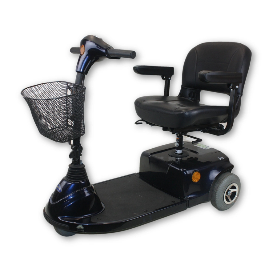
- Page 1 Lynx™L-3X Scooter DEALER: This manual MUST be given to the user of the product. User Manual USER: BEFORE using this product, read this manual and save for future reference.
-
Page 2: Table Of Contents
CONTENTS GENERAL Symbols ..................................................4 Limited Warranty ..............................................5 SAFETY General Guidelines ..............................................6 Operation Information ............................................7 EMI Information..............................................15 PRODUCT LABELING TECHNICAL DATA Typical Product Parameters ..........................................19 INSPECTION Safety Inspection Checklists ..........................................21 OPERATING THE POWERED SCOOTER Control Panel................................................24 Operating the Scooter............................................25 Engaging/Disengaging the Brake Release Lever....................................27 SEAT AND ARMS Removing/Installing the Seat ..........................................30 Adjusting Seat Height............................................31... - Page 3 CONTENTS WHEELS AND CASTERS Removing/Installing the Drive Wheels......................................36 Removing/Installing the Front Wheel........................................38 10 BATTERIES Recommended Battery Type ..........................................40 Removing/Installing the Batteries ........................................41 Connecting/Disconnecting the Battery Cables ....................................43 Charging the Batteries ............................................46 11 TRANSPORTING Transporting the Scooter.............................................49 12 ACCESSORIES Installing/Removing the Crutch/Cane Holder ....................................52 Installing/Removing the Safety Flag........................................53 Installing/Removing/Using the Walker Holder ....................................54 Installing/Removing the Rear Mounted Basket....................................55...
-
Page 4: General
1 GENERAL 1 General Symbols Warnings Signal words are used in this manual and apply to hazards or unsafe practices which could result in personal injury or property damage. See the information below for definitions of the signal words. DANGER Danger indicates an imminently hazardous situation which, if not avoided, will result in death or serious injury. -
Page 5: Limited Warranty
Invacare warrants all electronics and electrical components (excluding batteries), transaxle and frame to be free from defects in materials and workmanship for a period of twelve (12) months from the date of purchase from Invacare or a dealer. Invacare warrants all batteries to be free from defects in materials and workmanship for a period of six (6) months from the date of purchase from Invacare or a dealer. -
Page 6: Safety
NOTICE THE INFORMATION CONTAINED IN THIS DOCUMENT IS SUBJECT TO CHANGE WITHOUT NOTICE. Check all parts for shipping damage and test before using. In case of damage, DO NOT use. Contact Invacare/Carrier for further instruction. As a distributor of powered scooters, Invacare endeavors to supply a wide variety of powered scooters to meet many needs of the end user. -
Page 7: Operation Information
It is Invacare’s position that users of powered scooters should be transferred into appropriate seating in vehicles for transportation and use be made of the restraints made available by the auto industry. Invacare cannot and does not recommend any powered scooter transportation systems. - Page 8 Extreme caution is advised when moving an unoccupied powered scooter up or down the stairs. Invacare recommends disassembling the scooter and transporting the components independently up or down the stairs. ONLY use secure, non-detachable parts on each component for hand-hold supports.
-
Page 9: Repair Or Service Information
Use this information only as a “basic” guide. The techniques that are discussed have been used successfully by many. Individual users often develop skills to deal with daily living activities that may differ from those described in this manual. Invacare recognizes and encourages each individual to try what works best for him/her in overcoming obstacles that they may encounter;... - Page 10 ALWAYS wear your seat positioning strap. Inasmuch as the seat positioning strap is an option on this scooter (you may order with or without the seat positioning strap), Invacare strongly recommends ordering the seat positioning strap as an additional safeguard for the scooter user. The seat positioning strap is a positioning belt only. It is not designed for use as a safety device withstanding high stress loads such as auto or aircraft safety belts.
- Page 11 2 SAFETY WARNING Be aware that carrying heavy objects on your lap while occupying the scooter may adversely affect the stability of the scooter, resulting in serious bodily injury to the user, damage to the scooter and surrounding property. This scooter has been designed to accommodate one individual. If more than one individual occupies the scooter this may adversely affect the stability of the scooter, resulting in serious bodily injury to the user and passenger and damage to the scooter and surrounding property.
- Page 12 2 SAFETY WARNING When negotiating ramps, if the throttle control lever is released while in the forward motion, the powered scooter will roll back approximately one foot before the brake engages. If the throttle control lever is released while in the reverse motion, the powered scooter will roll back approximately three feet before the brake engages.
- Page 13 WARNING RAIN TEST Invacare has tested its powered scooters in accordance with ISO 7176 “Rain Test”. This provides the end user or his/her attendant sufficient time to remove his/her powered scooter from a rain storm and retain powered scooter operation.
-
Page 14: Weight Training
Check to ensure that all electrical connections are secure at all times. GROUNDING INSTRUCTIONS DO NOT, under any circumstances, cut or remove the round grounding prong from any plug used with or for Invacare products. Some devices are equipped with three-prong (grounding) plugs for protection against possible shock hazards. -
Page 15: Emi Information
2 SAFETY Weight Limitation WARNING The weight limitation is 300 lbs. Disposal WARNING This product has been supplied from an environmentally aware manufacturer that complies with the Waste Electrical and Electronic Equipment (WEEE) Directive 2002/96/CE. This product may contain substances that could be harmful to the environment if disposed of in places (landfills) that are not appropriate according to legislation. ... - Page 16 2 SAFETY The sources of radiated EMI can be broadly classified into three types: Hand-held Portable transceivers (transmitters-receivers with the antenna mounted directly on the transmitting unit. Examples include: citizens band (CB) radios, “walkie talkie”, security, fire and police transceivers, cellular telephones, and other personal communication devices). ...
- Page 17 2) This device has been tested to a radiated immunity level of 20 volts per meter. 3) The immunity level of the product is unknown. Modification of any kind to the electronics of this scooter as manufactured by Invacare may adversely affect the EMI immunity levels.
-
Page 18: Product Labeling
3 PRODUCT LABELING 3 Product Labeling WARNING DO NOT REMOVE THIS LABEL. The POSITIVE (+) RED battery cable MUST connect to the POSITIVE (+) battery terminal. The NEGATIVE (-) BLACK battery cable MUST connect to the NEGATIVE (-) battery terminal. DO NOT allow battery cables to contact the opposite battery terminal. -
Page 19: Technical Data
4 TECHNICAL DATA 4 Technical Data Typical Product Parameters Overall Dimensions LYNX L-3X Base Length: 44 in Base Width: 21.5 in Step Height (Floor Pan to Ground): 5 in Seat Height (Floor Pan to Seat Cushion): 16 in Overall Height:... - Page 20 4 TECHNICAL DATA Wheels LYNX L-3X Front Wheel: 8 in x 2 in Drive Wheel: 9 in x 2 in Driving LYNX L-3X Speed Range: 0 - 5 mph Maximum Incline Capability: 8° Grade Turning Radius: 44.7 in Weight LYNX L-3X...
-
Page 21: Inspection
5 INSPECTION 5 Inspection Safety Inspection Checklists Every six months take your powered scooter to a qualified technician for a thorough inspection and servicing. Regular cleaning will reveal loose or worn parts and enhance the smooth operation of your powered scooter. To operate properly and safely, your powered scooter must be cared for just like any other vehicle. - Page 22 5 INSPECTION Inspect/Adjust Initially ❑ Ensure powered scooter drives straight (no excessive drag or pull to one side). ❑ Check frame for damage and corrosion. ❑ Ensure that the brake release lever is easy to engage/disengage. ❑ Ensure that tiller adjustment mechanism engages and disengages properly and securely. ❑...
- Page 23 5 INSPECTION Inspect/Adjust Monthly ❑ Check brake for binding or interference with travel. ❑ Inspect front wheel/fork assembly for proper tension by spinning the wheel. The front wheel should come to a gradual stop. ❑ Tighten locknut if the front wheel wobbles noticeably or loosen locknut if the wheel binds to a stop. ❑...
-
Page 24: Operating The Powered Scooter
6 OPERATING THE POWERED SCOOTER 6 Operating the Powered Scooter Control Panel For this procedure, refer to FIGURE 6.1 on page 25. Speed Control Knob - The speed control knob is located on the right side of the control panel. The Turtle icon represents the slowest speed and the Rabbit icon represents the fastest speed. -
Page 25: Operating The Scooter
6 OPERATING THE POWERED SCOOTER Battery Charge Display Horn Button Service Indicator Speed Control Knob Throttle Control Lever FIGURE 6.1 Control Panel Operating the Scooter WARNING After any adjustments, repair or service and before use, make sure that all attaching hardware is tightened securely - otherwise injury or damage may result. - Page 26 6 OPERATING THE POWERED SCOOTER Before operating the powered scooter, review Control Panel on page 24. Install the batteries. Refer to Removing/Installing the Batteries on page 41. Charge the batteries. Refer to Charging the Batteries on page 46. Transferring to and from the seat can be accomplished in one of two ways: •...
-
Page 27: Engaging/Disengaging The Brake Release Lever
6 OPERATING THE POWERED SCOOTER To equip the scooter for left hand operation, contact a qualified technician. The powered scooter is equipped with a “proportional” control meaning that the farther you depress the throttle control lever, the faster the powered scooter travels. - Page 28 6 OPERATING THE POWERED SCOOTER Pull Up to Disengage (Push) Brake Release Lever Push Down to Engage (Drive) FIGURE 6.2 Engaging/Disengaging the Brake Release Lever Lynx™L-3X Scooter Part No. 1145807...
-
Page 29: Seat And Arms
7 SEAT AND ARMS 7 Seat and Arms WARNING After any adjustments, repair or service and before use, make sure that all attaching hardware is tightened securely - otherwise injury or damage may result. Before performing any maintenance, adjustment or service, turn power off and remove key from ignition. ... -
Page 30: Removing/Installing The Seat
7 SEAT AND ARMS Removing/Installing the Seat WARNING Before use, ensure that the seat is in the locked position. The seat lever MUST be pulled up to the 90° position to allow the seat to drop into the locked position. Otherwise, a fall from the scooter could occur causing bodily injury and/or damage to the scooter. -
Page 31: Adjusting Seat Height
7 SEAT AND ARMS Adjusting Seat Height For this procedure, refer to FIGURE 7.2. Remove the seat. Refer to Removing/Installing the Seat on page 30. Seat Post Remove the mounting bolt, two curved washers and lock nut securing the seat post to the frame tube. Align the frame tube mounting hole with one of three seat post Frame Tube mounting holes to achieve desired seat height. -
Page 32: Adjusting 90° Seat Swivel
7 SEAT AND ARMS Adjusting 90° Seat Swivel Top View WARNING Ensure that seat is locked into the forward position before and during operation of the scooter. Otherwise, injury to the user and/or Seat damage to the scooter may result. CAUTION Use the seat swivel option with caution when accessories are installed (such as safety flag,... -
Page 33: Adjusting The Seat Slide
7 SEAT AND ARMS Adjusting the Seat Slide Top View For this procedure, refer to FIGURE 7.4. Lift the seat slide lever located on the right side of the seat. Slide the seat forward or back to the desired position. Seat Release the seat slide lever and allow the seat to lock into position. -
Page 34: Adjusting The Arm Width
7 SEAT AND ARMS Adjusting the Arm Width For this procedure, refer to FIGURE 7.5. When installing the arms during set up, the four mounting screws are installed on the seat hinge for shipping purposes. Loosen the knob securing the arm tube to the seat frame. Push the arm in or out to the desired position. -
Page 35: Tiller Adjustment
8 TILLER ADJUSTMENT 8 Tiller Adjustment Adjusting the Tiller Angle WARNING Before performing any maintenance, adjustment or service, turn power Off and remove key from ignition. Ensure that tiller is properly adjusted before driving the scooter. After making any tiller angle adjustments and before use, the tiller MUST be securely locked into position. Otherwise, a fall from the scooter could occur causing bodily injury and/or damage to the scooter. -
Page 36: Wheels And Casters
9 WHEELS AND CASTERS 9 Wheels and Casters WARNING After any adjustments, repair or service and before use, make sure that all attaching hardware is tightened securely - otherwise injury or damage may result. Before performing any maintenance, adjustment or service, turn power Off and remove key from ignition. Removing/Installing the Drive Wheels ... - Page 37 9 WHEELS AND CASTERS Installing Place keystock in cutout on drive shaft as shown in FIGURE 9.1. Scooter not shown. The keystock in the drive shaft MUST lineup with the cutout in the wheel hub. Keystock If necessary, use a rubber hammer to gently tap drive wheel completely into position on the drive shaft.
-
Page 38: Removing/Installing The Front Wheel
9 WHEELS AND CASTERS Removing/Installing the Front Wheel For this procedure, refer to FIGURE 9.2. Take note of position and orientation of wheel and mounting hardware before removing. Removing Fork Fork Turn power off and remove the key from the ignition. Mounting Fork Place the front of the powered scooter up on blocks so that the... -
Page 39: Batteries
DO NOT tip the batteries. Keep the batteries in an upright position. Invacare strongly recommends that battery installation and battery replacement always be done by a qualified technician. All battery terminals caps (two on the left battery and two on the right battery) MUST be installed prior to use. -
Page 40: Recommended Battery Type
10 BATTERIES 10.1 Recommended Battery Type WARNING The warranty and performance specifications contained in this manual are based on the use of AGM batteries. Invacare strongly recommends their use as the power source for this unit. CAUTION Failure to use the correct battery size and/or voltage may cause damage to the powered scooter and give unsatisfactory performance. -
Page 41: Removing/Installing The Batteries
10 BATTERIES 10.2 Removing/Installing the Batteries For this procedure, refer to FIGURE 10.3 on page 45. Removing Place the powered scooter in a well ventilated area. CAUTION Work should be performed in an area without risking damage to carpeting or floor covering. Turn power off and remove the key from the ignition. - Page 42 10 BATTERIES Perform the following to install a battery from the battery tray: With the battery terminals facing towards the center of the scooter, position the battery onto the battery tray. Position the hook and loop fastening battery strap around the battery and to secure the battery to the battery tray. Repeat STEP 6 to install the remaining battery into the battery tray.
-
Page 43: Connecting/Disconnecting The Battery Cables
10 BATTERIES 10.3 Connecting/Disconnecting the Battery Cables WARNING Battery terminal configuration shown below MUST be used. Batteries that have the reversed terminal configuration MUST NOT be used - otherwise serious injury or damage may occur. DO NOT USE NEGATIVE (-) NEGATIVE (-) Battery Terminal Battery... - Page 44 10 BATTERIES RED battery terminal cap onto RED battery cable. GREY battery terminal cap onto BLACK battery cable. WARNING When connecting the battery cables to the batteries, the battery cables MUST be connected to the battery terminals/posts as shown in FIGURE 10.3, otherwise damage to the battery cable may result when installing battery terminal caps.
- Page 45 10 BATTERIES Disconnecting WARNING The use of rubber gloves and chemical goggles and face shield is recommended when working with batteries. NEVER allow any of your tools and/or battery cable(s) to contact both battery terminal(s)/post(s) at the same time. An electrical short may occur and serious personal injury or damage may occur.
-
Page 46: Charging The Batteries
10 BATTERIES 10.4 Charging the Batteries WARNING NEVER attempt to recharge the batteries by attaching cables directly to the battery terminals or clamps. DO NOT attempt to recharge the batteries and operate the powered scooter at the same time. Only use the provided charger with this product. CAUTION New batteries MUST be fully charged prior to initial use of the powered scooter. - Page 47 10 BATTERIES The battery charger light will be YELLOW or RED. Allow the batteries to charge until the charger light turns GREEN. Perform one of the following: • Battery charger light turns GREEN - Unplug the charger cable from the scooter and the wall outlet. •...
- Page 48 10 BATTERIES Trunk Lid Connect to Scooter Charger Cable Battery Charger Port Connect to Wall Outlet Charger Cable FIGURE 10.4 Charging the Batteries Lynx™L-3X Scooter Part No. 1145807...
-
Page 49: Transporting
11 TRANSPORTING 11 Transporting WARNING After any adjustments, repair or service and before use, make sure that all attaching hardware is tightened securely - otherwise injury or damage may result. Before performing any maintenance, adjustment or service, turn power off and remove key from ignition. DO NOT lift the scooter by the rear shroud - otherwise damage to the scooter may occur. - Page 50 11 TRANSPORTING Hold the seat post and align the curved locking brackets on the front frame assembly with the rear frame assembly pins. While holding the seat post, slowly lower the front frame assembly onto the rear frame assembly pins until the release lever locks. Connect the tiller wiring connector to the controller wiring connector.
-
Page 51: Accessories
12 ACCESSORIES 12 Accessories WARNING After any adjustments, repair or service and before use, make sure that all attaching hardware is tightened securely - otherwise injury or damage may result. Before performing any maintenance, adjustment or service, turn power off and remove key from ignition. ... -
Page 52: Installing/Removing The Crutch/Cane Holder
12 ACCESSORIES 12.1 Installing/Removing the Crutch/Cane Holder WARNING The installation of the crutch/cane holder onto the back of the scooter seat significantly increases the length of the scooter. When turning the scooter or swiveling the scooter seat, it is important to take note of this increased length - otherwise, injury and/or damage to the surrounding property may result. -
Page 53: Installing/Removing The Safety Flag
12 ACCESSORIES 12.2 Installing/Removing the Safety Flag WARNING The installation of the safety flag onto the back of the scooter seat significantly increases the length of the scooter. When turning the scooter or swiveling the scooter seat, it is important to take note of this increased length - otherwise, injury and/or damage to the surrounding property may result. -
Page 54: Installing/Removing/Using The Walker Holder
12 ACCESSORIES 12.3 Installing/Removing/Using the Walker Holder WARNING After ANY adjustments, repair or service and before use, make sure that all attaching hardware is tightened securely. The installation of the walker holder onto the back of the scooter seat significantly increases the length of the scooter. When turning the scooter or swiveling the scooter seat, it is important to take note of this increased length - otherwise, injury and/or damage to the surrounding property may result. -
Page 55: Installing/Removing The Rear Mounted Basket
12 ACCESSORIES 12.4 Installing/Removing the Rear Mounted Basket WARNING The rear mounted basket is rated for a maximum capacity of ten lbs. After ANY adjustments, repair or service and before use, make sure that all attaching hardware is tightened securely. The installation of the basket and basket bracket onto the back of the scooter seat increases the length of the scooter. -
Page 56: Maintenance
13 MAINTENANCE 13 Maintenance WARNING After any adjustments, repair or service and before use, make sure that all attaching hardware is tightened securely - otherwise, injury or damage may occur. Before performing any maintenance, adjustment or service, turn power Off and remove key from ignition. DO NOT overtighten hardware attaching to the frame. -
Page 57: Troubleshooting
14 TROUBLESHOOTING 14 Troubleshooting 14.1 General Troubleshooting SYMPTOM PROBABLE CAUSE SOLUTION Limited Driving Distance. Battery not charged long enough. Charge batteries overnight or ensure eight hours of charge between use. Batteries weak, won’t hold charge. Replace batteries. Refer to Removing/Installing the Battery Box on page 30. - Page 58 14 TROUBLESHOOTING SYMPTOM PROBABLE CAUSE SOLUTION Scooter will not drive. Error Check service indicator light on control panel (FIGURE 6.1 on page 25). If flashing, count the number of flashes and refer to Service Indicator Error Codes on page 59. Brake release lever disengaged. Engage brake release lever.
-
Page 59: Service Indicator Error Codes
14 TROUBLESHOOTING 14.2 Service Indicator Error Codes For the following table, refer to FIGURE 6.1 on page 25. FLASH DESCRIPTION MEANING Batteries need charging. Recharge the batteries. Refer to Removing/Installing the Batteries on page 35. Low battery voltage. Recharge the batteries before using. Refer to Charging the Batteries on page 40. Battery voltage too high. - Page 60 Invacare. Trademarks are identified by ™ and ®. All trademarks are owned by or licensed to Invacare Corporation or its subsidiaries unless otherwise noted. For more information regarding Invacare products, parts, and Part No. 1145807 Rev C - 02/10 services, please visit www.invacare.com.