Table of Contents
Advertisement
All manuals and user guides at all-guides.com
Owner's Operator And Maintenance Manual
Manuel De L'Utilisateur Et D'Entretien
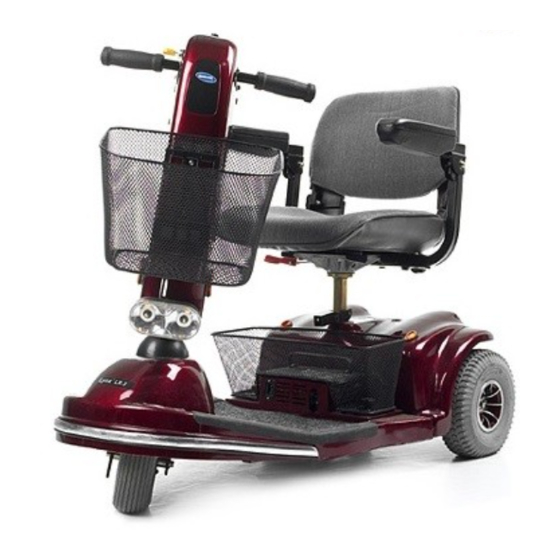
INVACARE SCOOTERS
LYNX
TM
LYNX LX-3
PANTHER LX-4
PANTHER MX-4
*DEALER: THIS MANUAL MUST BE
GIVEN TO THE USER OF THE SCOOTER.
USER: BEFORE USING THIS SCOOTER,
READ THIS MANUAL AND SAVE FOR
FUTURE REFERENCE.
ZOOM-3
/ PANTHER
LYNX SX-3
LYNX LX-3
FOURNISSEUR: CE MANUEL DOIT ÊTRE
REMIS À L'UTILISATEUR DU
TRIPORTEUR.
UTILISATEUR: AVANT D'UTILISER CE
TRIPORTEUR, LIRE CE MANUEL ET LE
CONSERVER À TITRE DE RÉFÉRENCE.
SERIES
TM
PLUS
Advertisement
Table of Contents

Related Manuals for Invacare Lynx Series


Summary of Contents for Invacare Lynx Series
- Page 1 All manuals and user guides at all-guides.com Owner's Operator And Maintenance Manual Manuel De L'Utilisateur Et D'Entretien INVACARE SCOOTERS ZOOM-3 LYNX / PANTHER SERIES LYNX SX-3 LYNX LX-3 LYNX LX-3 PLUS PANTHER LX-4 PANTHER MX-4 *DEALER: THIS MANUAL MUST BE FOURNISSEUR: CE MANUEL DOIT ÊTRE...
- Page 2 All manuals and user guides at all-guides.com WARNING WARNING WARNING WARNING WARNING SPECIAL NOTES NOTICE WARNING...
-
Page 3: Table Of Contents
All manuals and user guides at all-guides.com TABLE OF CONTENTS GENERAL GUIDELINES ........................... 6 SAFETY HANDLING ..........................10 WARNING/CAUTION LABEL LOCATION ..................11 SAFETY INSPECTION CHECKLIST ....................12 MAINTENANCE ............................13 TROUBLESHOOTING ..........................14 CONTROL PANEL FEATURES ......................15 OPERATION OF THE SCOOTER ....................... 17 USING THE HAND BRAKE LEVER/BRAKE ARM ................ - Page 4 All manuals and user guides at all-guides.com REMOVING/INSTALLING THE REAR SHROUD ................34 REPLACING FOAM FILLED TIRES ONTO WHEEL RIMS ............34 REMOVING/INSTALLING THE REAR WHEELS ................34 REMOVING/INSTALLING THE FRONT WHEELS ................. 36 TRANSPORTING THE SCOOTER...................... 37 REMOVING/INSTALLING THE FRONT BASKET ................39 REMOVING/INSTALLING THE FLOOR BASKET ................
- Page 5 All manuals and user guides at all-guides.com SPECIFICATIONS Plus 39.5-inches 43.5-inches 47-inches 47-inches 22-inches 23-inches 25-inches 25-inches 2.5-inches 3.5-inches 3-inches 3-inches 14-1/2-inches 14-1/2-inches 14-1/2-inches 14-1/2-inches 15-inches 15-1/2-inches 15-1/2-inches 15-1/2-inches 16-inches 16-1/2-inches 16-1/2-inches 16-1/2-inches 17-1/2-inches 15-inches 15-inches 16-inches 16-inches 17-inches 17-inches 18-inches 18-inches 26 - 28-inches...
- Page 6 All manuals and user guides at all-guides.com SPECIFICATIONS (continued)
- Page 7 All manuals and user guides at all-guides.com GENERAL WARNINGS...
- Page 8 All manuals and user guides at all-guides.com GENERAL WARNINGS (CONTINUED)
- Page 9 All manuals and user guides at all-guides.com GENERAL WARNINGS (CONTINUED) Plus EMI WARNINGS...
- Page 10 All manuals and user guides at all-guides.com EMI WARNINGS (CONTINUED)
- Page 11 All manuals and user guides at all-guides.com EMI WARNINGS (CONTINUED)
-
Page 12: Safety Handling
All manuals and user guides at all-guides.com SAFETY/HANDLING STABILITY AND BALANCE WARNING PERCENTAGE OF WEIGHT DISTRIBUTION WARNING... - Page 13 All manuals and user guides at all-guides.com STAIRWAYS WARNING ESCALATORS? SORRY! WARNING...
-
Page 14: Warning/Caution Label Location
All manuals and user guides at all-guides.com WARNING/CAUTION LABEL LOCATION WARNING WARNING WARNING WARNING WARNING WARNING 60106X144 1090105 WARNING WARNING WARNING WARNING WARNING CAUTION CAUTION CAUTION CAUTION CAUTION 1089265 1090104... -
Page 15: Safety Inspection Checklist
All manuals and user guides at all-guides.com This Procedure Includes the Following: Safety Inspection Checklist Maintenance Troubleshooting... -
Page 16: Maintenance
All manuals and user guides at all-guides.com MAINTENANCE WARNING CAUTION SUGGESTED MAINTENANCE PROCEDURES... - Page 17 All manuals and user guides at all-guides.com LUBRICATION POINTS (FIGURE 1) ® Seat Plate DETAIL "A" Seat Adaptor Connecting Release Seat Lever...
-
Page 18: Troubleshooting
All manuals and user guides at all-guides.com TROUBLESHOOTING GUIDE... -
Page 19: Control Panel Features
All manuals and user guides at all-guides.com This Procedure Includes the Following: Control Panel Features Operation of the Scooter Using the Hand Brake Lever/Brake Arm Brake Release Lever Reset Circuit Breaker/Fuse Replacement WARNING CONTROL PANEL FEATURES ALL SCOOTER MODELS With Delta or Standard Tillers (FIGURE 1). - Located on the top face of the control panel. - Page 20 All manuals and user guides at all-guides.com Speed Control Knob Battery Charge Battery Indicator Charge Indicator Speed Control Knob Battery Charge Indicator Horn Button With Standard Tillers (FIGURE 2). - Located on right side of the tiller control panel (DETAIL "C"). - Located on the front face of the control panel on ALL models EXCEPT LYNX SX-3 (DETAIL "D").
- Page 21 All manuals and user guides at all-guides.com With Delta Tillers (FIGURE 3). Head Light Button Ignition Forward/Reverse Reverse/Forward Throttle Control Lever Throttle Control Lever PANTHER MX-4 SCOOTERS ONLY With Standard Tillers (FIGURE 4) Turn Signal Switch Hazard Light Button Hand Brake Lever High/Low Speed Switch...
-
Page 22: Operation Of The Scooter
All manuals and user guides at all-guides.com OPERATION OF THE SCOOTER (FIGURES 1-5) WARNING WARNING... -
Page 23: Using The Hand Brake Lever/Brake Arm
All manuals and user guides at all-guides.com USING THE HAND BRAKE LEVER/BRAKE ARM (FIGURE 6) CAUTION HAND BRAKE LEVER BRAKE ARM... -
Page 24: Brake Release Lever
All manuals and user guides at all-guides.com BRAKE RELEASE LEVER CAUTION Brake Arm ALL MODELS EXCEPT PANTHER MX-4 (FIGURE 7) Brake Release Lever Rear of Scooter PANTHER MX-4 ONLY (FIGURE 8) Rear of Scooter Brake Release Lever... -
Page 25: Reset Circuit Breaker/Fuse Replacement
All manuals and user guides at all-guides.com RESET CIRCUIT BREAKER/FUSE REPLACEMENT (FIGURE 9) CIRCUIT BREAKER FUSE REPLACEMENT Circuit Breaker Rear Button Shroud Fuse Holder Fuse... -
Page 26: Removing/Installing The Batteries With Cables
All manuals and user guides at all-guides.com This Procedure Includes the Following: Removing/Installing the Batteries with Cables Replacing the Batteries Charging the Batteries WARNING REMOVING/INSTALLING THE BATTERIES WITH CABLES (FIGURE 1) REMOVING WARNING Top Battery Battery Wiring Harness Red Connector Fastening Strap Black Connector... - Page 27 All manuals and user guides at all-guides.com REPLACING THE BATTERIES (FIGURE 2) WARNING CAUTION RECOMMENDED BATTERY TYPES WARNING CAUTION Plus...
- Page 28 All manuals and user guides at all-guides.com WARNING CAUTION Plus CAUTION WARNING Plus...
- Page 29 All manuals and user guides at all-guides.com Plus Battery Cable Battery Battery Connector Terminal Mounting Screw Cable Battery Battery Battery Cable Boot Terminal Locknut Battery Battery Cable Battery Cable Boot Lockwasher Mounting Locknut Mounting Screw Battery Screw Cable Lockwasher Battery Boot Battery Washer...
-
Page 30: Charging The Batteries
All manuals and user guides at all-guides.com CHARGING THE BATTERIES WARNING CAUTION WARNING Plus... - Page 31 All manuals and user guides at all-guides.com REMOTE BATTERY CHARGER (FIGURE 3) 110-Volt Wall Outlet Charger Port Tiller Cover Charger AC Power Connector Charger Cord Charger Port ON-BOARD BATTERY CHARGER (FIGURE 4) Charger Port Chain Cover On-Board Battery Charger Floor Basket 110-Volt Wall Outlet...
- Page 32 All manuals and user guides at all-guides.com BATTERY CHARGER OPERATION (FIGURE 5) ON/OFF Indicator Light Charging Indicator Light ON/OFF Indicator Light Charging Indicator Light...
-
Page 33: Removing/Installing The Seat
All manuals and user guides at all-guides.com This Procedure Includes the Following: Removing/Installing the Seat Adjusting the Seat Height 90º Seat Swivel Adjustment Adjusting the Seat Depth Using the Adjustable Seat Slide Removing/Installing Seat Upholstery/Cushion WARNING REMOVING/INSTALLING THE SEAT DETERMINING SEAT POST TYPE (FIGURE 1) - Page 34 All manuals and user guides at all-guides.com REMOVING (FIGURE 2) CAUTION Seat Stability Knob Frame Seat Post Post Seat Height Adjustment Pin INSTALLING (FIGURE 2) Adjustable Height Seat WARNING Post Pin Lock Bend End of Pin Lock AWAY From Pin WARNING...
-
Page 35: Adjusting The Seat Height
All manuals and user guides at all-guides.com ADJUSTING THE SEAT HEIGHT WARNING SOLID SEAT POST (FIGURE 3) Frame Post Stability Knob Mounting Screw Height Adjustment Plus Holes Front Frame Locknut Assembly... - Page 36 All manuals and user guides at all-guides.com ADJUSTABLE HEIGHT SEAT POST (FIGURE 4) WARNING zoom-3 ALL other models Adjustable Height Seat Post Seat Height CAUTION Adjust- ment Pin Frame Pin Lock Post Bend End of Pin Lock AWAY From Pin...
-
Page 37: 90º Seat Swivel Adjustment
All manuals and user guides at all-guides.com 90º SEAT SWIVEL ADJUSTMENT ALL MODELS EXCEPT ZOOM-3 (FIGURE 5) WARNING CAUTION Seat Seat Swivel Release Lever (Lift UP to activate) ADJUSTING THE SEAT DEPTH ALL MODELS EXCEPT ZOOM-3 (FIGURE 6) -
Page 38: Using The Adjustable Seat Slide
All manuals and user guides at all-guides.com Mounting Positions Seat WARNING Seat Stand Cutout Slot Swivel Cutout Lever Slot Washer Seat Swivel Lockwasher Assembly Shorter Mounting Longer Mounting Screw Screws (NOTE: Only one (1) shown for clarity) USING THE ADJUSTABLE SEAT SLIDE (FIGURE 7) Release Lever Seat... -
Page 39: Removing/Installing The Seat Upholstery/Cushion
All manuals and user guides at all-guides.com REMOVING/INSTALLING THE SEAT UPHOLSTERY/ CUSHION (FIGURE 8) Seat Seat Upholstery REMOVING Seat Cushion INSTALLING Seat Snap Upholstery Buttons WARNING... -
Page 40: Folding/Unfolding The Back
All manuals and user guides at all-guides.com This Procedure Includes the Following: Folding/Unfolding the Back Removing/Installing the Back Cushion/Upholstery Adjusting the Back Recline Adjusting the Headrest WARNING Seat FOLDING/UNFOLDING THE Back BACK (FIGURE 1) REMOVING/INSTALLING BACK CUSHION/UPHOLSTERY (FIGURE 2) WARNING Back Cushion w/Foam Insert Back... -
Page 41: Adjusting The Back Recline
All manuals and user guides at all-guides.com ADJUSTING THE BACK RECLINE ALL MODELS EXCEPT ZOOM-3, SX-3 AND LX-3 (FIGURE 3) Mounting Back Screw Bracket WARNING Outside Jam Nut Top Edge of Back Bracket Inside Jam Nut ADJUSTING THE HEADREST ALL MODELS EXCEPT ZOOM-3 (FIGURE 4) Headrest Release Headrest... -
Page 42: Armrest Angle Adjustment
All manuals and user guides at all-guides.com This Procedure Includes the Following: Armrest Angle Adjustment Armrest Width Adjustment Armrest Depth/Height Adjustment WARNING ARMREST ANGLE ADJUSTMENT ALL SEATS BUILT AFTER 10/ Armrest 00 AND CONTOUR SEATS BUILT BEFORE 10/00 (FIGURE 1) Mounting Screw Adjustment... -
Page 43: Armrest Depth/Heightadjustment
All manuals and user guides at all-guides.com ARMREST DEPTH/HEIGHT ADJUSTMENT ALL MODELS EXCEPT ZOOM-3 (FIGURE 3) DEPTH Armrest Bottom Adjustment Knob HEIGHT (FIGURE 4) Armrest Locknut Mounting Screw Stability Armpost Set Screws... -
Page 44: Tiller Angle Adjustment
All manuals and user guides at all-guides.com This Procedure Includes the Following: Tiller Angle Adjustment WARNING TILLER ANGLE ADJUSTMENT WARNING FOLD DOWN TILLER ZOOM-3 (FIGURE 1) Tiller Adjustment Tiller Knob Spacer Tiller Adjustment Plate Tiller Bracket... - Page 45 All manuals and user guides at all-guides.com ALL OTHER MODELS (FIGURE 2) Plus Tiller Tiller Release Lever UNLOCKED Tiller Release Lever LOCKED Adjustment Pin Tiller Adjustment Plate...
-
Page 46: Removing/Installing The Rear Shroud
All manuals and user guides at all-guides.com This Procedure Includes the Following: Removing/Installing the Rear Shroud Replacing Foam Filled Tires Onto Wheel Rims Removing/Installing the Rear Wheels Removing/Installing the Front Wheel WARNING REMOVING/INSTALLING THE REAR SHROUD (FIGURE 1) REMOVING CAUTION Rear Shroud Battery Wiring... - Page 47 All manuals and user guides at all-guides.com REMOVING/INSTALLING THE REAR WHEELS (FIGURE 2) REMOVING WARNING INSTALLING WARNING...
-
Page 48: Removing/Installing The Front Wheels
All manuals and user guides at all-guides.com Rear Wheel Tab Bent 90° Large Washer Keystock Cutout Locking Tab Washer Wheel Hub Locking Tab Washer Drive Shaft Lockwasher Hex Screw Mounting Screws REMOVING/INSTALLING THE FRONT WHEELS (FIGURE 3) WARNING... - Page 49 All manuals and user guides at all-guides.com REMOVING Plus INSTALLING WARNING Plus Plus Mounting Mounting Screw Mounting Fork Fork Hex Head Lockwasher Mounting Threaded Screw Insert Washer Locknut Wheel Wheel Washers Spacer Spacer Washer Panther (MX4) Lockwasher Front Mounting Frame Screw Wheel...
-
Page 50: Transporting The Scooter
All manuals and user guides at all-guides.com This Procedure Includes the Following: Transporting the Scooter WARNING TRANSPORTING THE SCOOTER (FIGURES 1 AND 2) DISASSEMBLING THE SCOOTER... - Page 51 All manuals and user guides at all-guides.com Yellow Connectors Controller Wiring Harness Tiller Wiring Harness Blue Connectors Wire Supports ORANGE Connectors Controller Wiring Harness Tiller Wiring Harness Plus...
- Page 52 All manuals and user guides at all-guides.com WARNING Rear Sub Frame Retaining Pin Threaded End of Cable Assembly Hand Brake Cable Assembly Frame Tab of Rear Sub-Frame Retaining Tab Locknut Hand Brake Cable Threaded End of Hand Brake Cable Assembly Rear Frame Tab Rear Wheel...
- Page 53 All manuals and user guides at all-guides.com WARNING Retaining Front Frame Assembly Rear Frame Assembly Front Basket Seat Rear Shroud Front Sub-Frame Assembly Batteries One Piece Frame Assembly Rear Sub-Frame Assembly...
-
Page 54: Removing/Installing The Front Basket
All manuals and user guides at all-guides.com This Procedure Includes the Following: Removing/Installing the Front Basket Removing/Installing the Floor Basket Removing/Installing the Seat Positioning Straps Removing/Installing the Crutch/Cane Holder Removing/Installing the Safety Flag Replacing the Anti-Tipper Wheel and Anti-Tipper Wheel Assembly Replacing Seat Lever Replacing Tiller Angle Adjustment Lever Replacing Headlight Lightbulbs... -
Page 55: Removing/Installing The Floor Basket
All manuals and user guides at all-guides.com REMOVING/INSTALLING THE FLOOR BASKET (FIGURE 2) Thumb Front Floor Screws Shroud Basket Rear Shroud Floor Vertical Basket Side Front Shroud REMOVING/INSTALLING THE SEAT POSITIONING STRAP (FIGURE 3) INSTALLING 1. Remove the width adjustment knob that is located either underneath or on the back of the seat frame. -
Page 56: Removing/Installing The Crutch/Cane Holder
All manuals and user guides at all-guides.com REMOVING/INSTALLING THE CRUTCH/CANE HOLDER (FIGURE 4) Seat WARNING Crutch/ Cane Holder Hook Mounting Accessory Screw Tube Base INSTALLING 1. Install the crutch/cane holder into the accessory tube located on the back of the seat. -
Page 57: Replacing Anti-Tipper Wheels And Anti-Tipper Wheel Assembly
All manuals and user guides at all-guides.com REPLACING ANTI-TIPPER WHEELS AND ANTI-TIPPER WHEEL ASSEMBLY (FIGURE 6) WARNING ANTI-TIPPER WHEELS 1. Perform one of the following: A. For - remove the screw and locknut that secures the anti- Frame tipper wheels to the frame. Locknut B. -
Page 58: Replacing Seat Lever
All manuals and user guides at all-guides.com REPLACING SEAT LEVER (FIGURE 7) Seat Plate Mounting Screw Seat Lever Locknut Bottom Hole Hole Cotter Pin Connecting... -
Page 59: Replacing Tiller Angle Adjustment Lever
All manuals and user guides at all-guides.com REPLACING TILLER ANGLE ADJUSTMENT LEVER (FIGURE 8) Seat Plunger Tiller Lever Adjustment Holes Retaining Ring Position tiller in-between Adjustment adjustment holes Holes (STEP 1) REPLACING HEADLIGHT LIGHTBULBS MODELS LYNX LX-3 AND PANTHER LX-4 (FIGURE 9) Mounting Screws Housing Lightbulb... - Page 60 All manuals and user guides at all-guides.com MODEL PANTHER MX-4 (FIGURE 10) Place scribe mark near corresponding slot of headlight assembly. Place scribe mark on Partial View of prong. Headlight Assembly Lightbulb Plug Notch Headlight Assembly Prong Lightbulb Plug Prongs...
-
Page 61: Replacing On-Board Battery Charger
All manuals and user guides at all-guides.com REPLACING ON-BOARD BATTERY CHARGER (FIGURE 11) On-Board Battery Charger White Connectors Blue Connectors Front Shroud... - Page 62 All manuals and user guides at all-guides.com NOTES...
- Page 63 All manuals and user guides at all-guides.com LIMITED WARRANTY...
- Page 64 All manuals and user guides at all-guides.com Invacare Corporation Canada...