Table of Contents
Advertisement
www.proform.com
USER'S MANUAL
Model No. PFEL02915.0
Serial No.
Write the serial number in the space
above for reference.
Serial Number Decal
(under frame)
ACTIVATE YOUR
WARRANTY
To register your product and
activate your warranty today,
go to www.proformservice.com/
registration.
CUSTOMER CARE
For service at any time, go to
www.proformservice.com.
Or call 1-888-533-1333
Mon.–Fri. 6 a.m.–6 p.m. MT
Sat. 8 a.m.–12 p.m. MT
Please do not contact the store.
CAUTION
Read all precautions and instruc-
tions in this manual before using
this equipment. Keep this manual
for future reference.
Advertisement
Table of Contents

Related Manuals for Pro-Form 225 CSE


Summary of Contents for Pro-Form 225 CSE
- Page 1 www.proform.com USER’S MANUAL Model No. PFEL02915.0 Serial No. Write the serial number in the space above for reference. Serial Number Decal (under frame) ACTIVATE YOUR WARRANTY To register your product and activate your warranty today, go to www.proformservice.com/ registration. CUSTOMER CARE For service at any time, go to www.proformservice.com.
-
Page 2: Table Of Contents
TABLE OF CONTENTS WARNING DECAL PLACEMENT ............. . .2 IMPORTANT PRECAUTIONS . -
Page 3: Important Precautions
IMPORTANT PRECAUTIONS WARNING: To reduce the risk of serious injury, read all important precautions and instructions in this manual and all warnings on your elliptical before using your elliptical. ICON assumes no responsibility for personal injury or property damage sustained by or through the use of this product. - Page 4 STANDARD SERVICE PLANS...
-
Page 5: Before You Begin
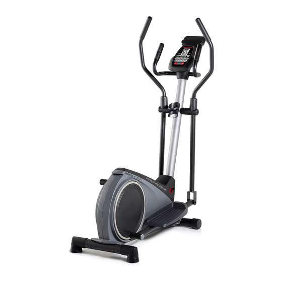
225 CSE manual. To help us assist you, note the product model ® elliptical. The 225 CSE provides a selection of features number and serial number before contacting us. The designed to make your workouts at home more effec- model number and the location of the serial number tive and enjoyable. -
Page 6: Part Identification Chart
PART IDENTIFICATION CHART Use the drawings below to identify the small parts needed for assembly. The number in parentheses below each drawing is the key number of the part, from the PART LIST near the end of this manual. The number following the key number is the quantity needed for assembly. -
Page 7: Assembly
ASSEMBLY • To hire an authorized service technician to • In addition to the included tool(s), assembly assemble this product, call 1-800-445-2480. requires the following tools: one adjustable wrench • Assembly requires two persons. one Phillips screwdriver • Place all parts in a cleared area and remove the packing materials. - Page 8 3. Orient the Rear Stabilizer (9) as indicated by the sticker. While a second person lifts the rear of the Frame (1), attach the Rear Stabilizer (9) to the Frame with two M10 x 68mm Screws (34). 4. Orient the Upright (2) and the Top Shield (41) as shown.
- Page 9 5. See the inset drawing. Locate the wire tie in the lower end of the Upright (2). Tie the wire tie to the Wire Harness (73). Next, pull the upper end of the wire tie until the Wire Harness is routed through the Upright.
- Page 10 7. The Console (23) can use four AA batteries (not included); alkaline batteries are recommended. Do not use old and new batteries together or alkaline, standard, and rechargeable batter- ies together. IMPORTANT: If the Console has been exposed to cold temperatures, allow it to warm to room temperature before you insert batteries.
-
Page 11: Attach The Front Upright Cover (81) To The
9. Insert the excess wire into the Upright (2) or into the Console (23). Avoid pinching Press the Rear Upright Cover (75) into the the wires Upright (2). Have a second person hold the Rear Upright Cover in place. Tip: Avoid pinching the wires. Attach the Console (23) to the Upright (2) with four M4 x 16mm Screws (52);... - Page 12 12. Identify the Right Upper Body Arm (8). Slide an Upper Body Arm Cover (42) upward onto the Right Upper Body Arm (8). Next, insert the Right Upper Body Arm (8) into an Upper Body Leg (5). Tip: Have a second person hold the Upper Body Arm Cover (42) while you perform this Hexagonal action:...
- Page 13 14. Orient an Upper Body Arm Spacer (47) as shown. Slide the Upper Body Arm Spacer onto the right side of the Pivot Axle (26). Next, slide the Right Upper Body Arm (8) onto the right side of the Pivot Axle (26). Repeat these actions on the other side of the elliptical.
- Page 14 16. Apply a small amount of grease to the axle on the Right Crank Arm (80). Slide the Right Pedal Arm (12) onto the axle on the Right Crank Arm (80). Next, slide an M10 x 28mm Washer (83) onto an M10 x 20mm Screw (40), and tighten the Screw into the axle.
- Page 15 18. Attach the Tablet Holder (32) to the back of the Console (23) with four M4 x 16mm Screws (52); start all the Screws, and then tighten them. 19. Make sure that all parts of the elliptical are properly tightened. Note: Extra parts may be included. To protect the floor or carpet from damage, place a mat under the elliptical.
-
Page 16: How To Use The Elliptical
HOW TO USE THE ELLIPTICAL HOW TO MOVE THE ELLIPTICAL HOW TO EXERCISE ON THE ELLIPTICAL Due to the size and weight of the elliptical, moving To mount the elliptical, hold the handlebars or the it requires two persons. Stand in front of the ellipti- upper body arms and step onto the pedal that is in the cal, hold the upright, and place one foot against one of lowest position. - Page 17 HOW TO LEVEL THE ELLIPTICAL HOW TO USE THE TABLET HOLDER If the elliptical rocks IMPORTANT: The tablet holder was designed for use with most full-size tablets and smart phones. slightly on your floor Do not place any other electronic device or object during use, turn one or both of the level- into the tablet holder.
- Page 18 CONSOLE DIAGRAM FEATURES OF THE CONSOLE The advanced console offers an array of features designed to make your workouts more effective and enjoyable. When you use the manual mode of the console, you can change the resistance of the pedals with the touch of a button.
- Page 19 HOW TO USE THE MANUAL MODE The upper display—This display will show your pedaling speed in revolutions per minute (RPM) 1. Turn on the console. and your power output in watts. The display will change every few seconds. Press any button or begin pedaling to turn on the console.
- Page 20 5. Measure your heart rate if desired. When your pulse is detected, your heart rate will be shown in the upper display. For the most accurate You can measure your heart rate using either the heart rate reading, hold the contacts for at least handgrip heart rate monitor or a compatible heart 15 seconds.
- Page 21 HOW TO USE A QUICK ONBOARD WORKOUT As you exercise, keep your pedaling speed within the target speed zone for the current segment by 1. Turn on the console. increasing or decreasing your pedaling speed or by increasing or decreasing the resistance of the Press any button or begin pedaling to turn on the pedals.
- Page 22 HOW TO CONNECT YOUR SMART DEVICE TO THE THE OPTIONAL CHEST HEART RATE MONITOR CONSOLE Whether your 1. Download and install the iFit app on your smart goal is to device. burn fat or to strengthen your On your iOS or Android™...
-
Page 23: Fcc Information
THE SETTINGS MODE the unit of measurement, press the 2 Quick Onboard Workouts button repeatedly. The console features a settings mode that allows you to select a unit of measurement for the console and to Note: When you replace the batteries, it may be neces- view console usage information. -
Page 24: Maintenance And Troubleshooting
MAINTENANCE AND TROUBLESHOOTING MAINTENANCE Note: For clarity, the right pedal disc is not shown in the drawing below. Regular maintenance is important for optimal per- formance and to reduce wear. Inspect and properly Locate the Reed Switch (53). Loosen, but do not tighten all parts each time the elliptical is used. - Page 25 HOW TO ADJUST THE DRIVE BELT Loosen the M8 x 22mm Screw (65), and turn the M10 x 60mm Bolt (62) until the Drive Belt (19) is tight. If you can feel the pedals slip while you are pedaling, even when the resistance is adjusted to the highest level, the drive belt may need to be adjusted.
-
Page 26: Exercise Guidelines
EXERCISE GUIDELINES Burning Fat—To burn fat effectively, you must exer- WARNING: cise at a low intensity level for a sustained period of Before beginning this time. During the first few minutes of exercise, your or any exercise program, consult your physi- body uses carbohydrate calories for energy. - Page 27 SUGGESTED STRETCHES The correct form for several basic stretches is shown at the right. Move slowly as you stretch; never bounce. 1. Toe Touch Stretch Stand with your knees bent slightly and slowly bend forward from your hips. Allow your back and shoulders to relax as you reach down toward your toes as far as possible.
- Page 28 NOTES...
-
Page 29: Part List
PART LIST Model No. PFEL02915.0 R0715A Key No. Qty. Description Key No. Qty. Description Frame Axle Cap Upright Upper Body Arm Spacer Left Shield Frame Spacer Right Shield Upper Body Arm Bushing Upper Body Leg M8 x 41mm Bolt Left Upper Body Arm M10 x 22mm Washer M10 x 74mm Bolt M4 x 16mm Screw... -
Page 30: Exploded Drawing
EXPLODED DRAWING A Model No. PFEL02915.0 R0715A... - Page 31 EXPLODED DRAWING B Model No. PFEL02915.0 R0715A...
-
Page 32: Ordering Replacement Parts
ORDERING REPLACEMENT PARTS To order replacement parts, please see the front cover of this manual. To help us assist you, be prepared to provide the following information when contacting us: • the model number and serial number of the product (see the front cover of this manual) •...