Table of Contents
Advertisement
Advertisement
Table of Contents
Troubleshooting

Related Manuals for Miller Electric Auto-Axcess 450


Summary of Contents for Miller Electric Auto-Axcess 450
- Page 1 Visit our website at www.MillerWelds.com/ams Auto-Axcess 450 File: Advanced Manufacturing Systems OM-210 540S 2007−10 Processes MIG (GMAW) Welding Pulsed MIG (GMAW-P) Flux Cored (FCAW) Welding Automatic Welding Description Automatic Welding Interface And Arc Welding Power Source...
- Page 2 ISO 9001:2000 Quality System Standard. particular model are also provided. Miller Electric manufactures a full line of welders and welding related equipment. For information on other quality Miller products, contact your local Miller distributor to receive the latest full line catalog or individual specification sheets.
-
Page 3: Table Of Contents
TABLE OF CONTENTS SECTION 1 − SAFETY PRECAUTIONS - READ BEFORE USING 1-1. Symbol Usage ............... . 1-2. - Page 4 TABLE OF CONTENTS SECTION 7 − TROUBLESHOOTING ............7-1.
-
Page 5: Section 1 − Safety Precautions - Read Before Using
DC constant voltage (wire) welder, 2) a DC manual (stick) welder, or 3) an AC welder with reduced open-circuit volt- age. In most situations, use of a DC, constant voltage wire welder is recommended. And, do not work alone! D Disconnect input power or stop engine before installing or servicing this equipment. - Page 6 OM-210 540 Page 2 D Do not use welder to thaw frozen pipes. D Remove stick electrode from holder or cut off welding wire at contact tip when not in use.
-
Page 7: Additional Symbols For Installation, Operation, And Maintenance
1-3. Additional Symbols For Installation, Operation, And Maintenance FIRE OR EXPLOSION hazard. D Do not install or place unit on, over, or near combustible surfaces. D Do not install unit near flammables. D Do not overload building wiring − be sure power supply system is properly sized, rated, and protected to handle this unit. -
Page 8: California Proposition 65 Warnings
1-4. California Proposition 65 Warnings Welding or cutting equipment produces fumes or gases which contain chemicals known to the State of California to cause birth defects and, in some cases, cancer. (California Health & Safety Code Section 25249.5 et seq.) Battery posts, terminals and related accessories contain lead and lead compounds, chemicals known to the State of California to cause cancer and birth defects or other... -
Page 9: Section 2 − Consignes De Sécurité − Lire Avant Utilisation
SECTION 2 − CONSIGNES DE SÉCURITÉ − LIRE AVANT UTILISATION Se protéger et protéger les autres contre le risque de blessure — lire et respecter ces consignes. 2-1. Symboles utilisés DANGER! − Indique une situation dangereuse qui si on l’évite pas peut donner la mort ou des blessures graves. Les dangers possibles sont montrés par les symboles joints ou sont expliqués dans le texte. - Page 10 Il reste une TENSION DC NON NÉGLIGEABLE dans les sources de soudage onduleur quand on a coupé l’alimentation. D Arrêter les convertisseurs, débrancher le courant électrique et décharger les condensateurs d’alimentation selon les instructions indiquées dans la partie Entretien avant de toucher les pièces. DES PIÈCES CHAUDES peuvent provoquer des brûlures graves.
-
Page 11: Dangers Supplémentaires En Relation Avec L'installation, Le Fonctionnement Et La Maintenance
ACCUMULATIONS risquent de provoquer des blessures ou même la mort. D Fermer l’alimentation du gaz protecteur en cas de non-utilisation. D Veiller toujours à bien aérer les espaces confi- nés ou se servir d’un respirateur d’adduction d’air homologué. LES CHAMPS MAGNETIQUES peuv- ent affecter des implants médicaux. -
Page 12: Proposition Californienne 65 Avertissements
LES FILS DE SOUDAGE peuvent provoquer des blessures. D Ne pas appuyer sur la gâchette avant d’en avoir reçu l’instruction. D Ne pas diriger le pistolet vers soi, d’autres per- sonnes ou toute pièce mécanique en enga- geant le fil de soudage. DES ORGANES MOBILES peuvent provoquer des blessures. -
Page 13: Principales Normes De Sécurité
2-5. Principales normes de sécurité Safety in Welding, Cutting, and Allied Processes, ANSI Standard Z49.1, de Global Engineering Documents (téléphone : 1-877-413-5184, site Internet : www.global.ihs.com). Recommended Safe Practices for the Preparation for Welding and Cut- ting of Containers and Piping, American Welding Society Standard AWS F4.1 de Global Engineering Documents (téléphone : 1-877-413-5184, site Internet : www.global.ihs.com). - Page 14 OM-210 540 Page 10...
-
Page 15: Section 3 − Installation
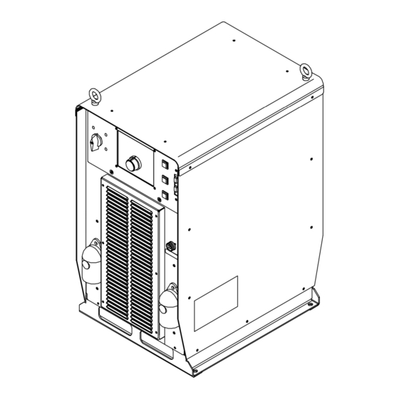
SECTION 3 − INSTALLATION Appearance of actual unit may vary from unit shown in manual. 3-1. Specifications Rated Wire Feed Input Voltage Welding Welding Speed Speed Power Power Range Range Output Output Range** Range** Three 450 A @ 10-44 Standard: Phase 44 V DC, 50-1400... -
Page 16: Duty Cycle And Overheating
3-3. Duty Cycle And Overheating 100% Duty Cycle At 450 Amperes Continuous Welding Overheating 3-4. Volt-Ampere Curves OM-210 540 Page 12 60% Duty Cycle At 580 Amperes 6 Minutes Welding Minutes CV MODE A M PE R A G E Duty Cycle is percentage of 10 min- utes that unit can weld at rated load without overheating. -
Page 17: Selecting A Location
3-5. Selecting A Location Movement Location Special installation may be required where gasoline or volatile liquids are present − see NEC Article 511 or CEC Section 20. 18 in (460 mm) 3-6. Connection Diagram Tipping 18 in (460 mm) Do not move or operate unit where it could tip. -
Page 18: Rear Panel Receptacles And Supplementary Protectors
3-7. Rear Panel Receptacles And Supplementary Protectors OM-210 540 Page 14 Receptacle single-phase power. Maximum output from RC2 is limited by supplementary protector CB1 to 10 amps. CB1 protects 115 volt receptacle RC2 from overload. If CB1 opens, RC2 does not work. -
Page 19: Connecting To Weld Terminals
3-8. Connecting To Weld Terminals If using an electrode negative (straight polarity) process, the volt sense lead must be connected to the work. Tools Needed: 3/4 in (19mm) Turn off power before connecting to weld output terminals. Failure to properly connect weld cables may cause excessive heat and start a fire, or damage your machine. -
Page 20: Selecting Weld Cable Sizes
3-9. Selecting Weld Cable Sizes* ARC WELDING can cause Electromagnetic Interference. To reduce possible interference, keep weld cables as short as possible, close together, and down low, such as on the floor. Locate welding operation 100 meters from any sensitive electronic equipment. Be sure this welding machine is installed and grounded according to this manual. -
Page 21: Peripheral Receptacle Functions
3-10. Peripheral Receptacle Functions Ref. 803 245-B *Circuit common is same electrical reference point. **Speed of Jog + (advance) and Jog − (retract) is 60 ipm for 3 seconds, then it automatically changes to 700 ipm. Note: A customer supplied matching amphenol plug, factory Part No. 194 847, [Amphenol Part No. 97-3106A-20-33P(B)(621) and strain relief clamp 97-3057-12(0621)] is required to use peripheral receptacle. -
Page 22: Motor Control Receptacle Functions
3-11. Motor Control Receptacle Functions OM-210 540 Page 18 Socket Not used. Motor negative (−). Tach A. Motor positive (+). Tach common. Gas valve. Electrode sense. Tach +5 volts dc. Tach B. Gas valve. Ref. 803 245-B Socket Information... -
Page 23: Electrical Service Guide
3-12. Electrical Service Guide Failure to follow these electrical service guide recommendations could create an electric shock or fire hazard. These recommenda- tions are for a dedicated branch circuit sized for the rated output and duty cycle of the welding power source. NOTICE −... -
Page 24: Connecting Input Power
3-13. Connecting Input Power Tools Needed: 5/16 in Turn Off welding power source, and check voltage on input capacitors according to Section 7-3 before proceeding. Installation must meet all National and Local Codes − have only qualified persons make this installation. Disconnect and lockout/tagout input power before... -
Page 25: Touch Sensor Operation
3-14. Touch Sensor Operation The touch sensor feature allows the robot to locate a weldment using the wire feed system and welding power source. The weld output terminals provide a path for touch sensor voltage when this feature is turned on at the peripheral receptacle. -
Page 26: Section 4 − Operation
SECTION 4 − OPERATION 4-1. Operational Terms The following is a list of terms and their definitions as they apply to this interface unit: General Terms: Synergic Synergic refers to the unit’s ability to use preprogrammed pulse parameters to determine the actual pulse settings of Peak Amperage, Background Amperage, Pulse Frequency and Pulse Width at any specific wire feed speed setting. - Page 27 4-1 . Operational Terms (Continued) Start Provides voltage/arc adjust, wire feed rate, and time value for modified arc starts (only available on Auto Axcess models in the Arc On and Analog input or the Arc On and No Analog input modes, and can only be set with the optional PDA with File Management software).
-
Page 28: Front Panel Controls (See Section 4-3)
4-2. Front Panel Controls (See Section 4-3) Program Process Wire Type Gas Type Setup Program Display Displays the number of the active program. Adjust Knob Turn the Adjust knob to change program number, Setup, Arc Control, and weld parameters. Program Push Button LED The LED lights when the Program Push Button is active. -
Page 29: Front Panel Controls - Continued (See Section 4-2)
4-3. Front Panel Controls - Continued (See Section 4-2) Arc Control LED The LED lights to indicate the Arc Control button is active. Light goes out when button is inactive. Arc Control Push Button This push button allows fine tuning inductance for MIG programs, and Arc Control for programs other than MIG. -
Page 30: Front Panel Switches
Manufacturer Fanuc Daihen Kawasaki Kuka Comau Hitachi Nachi Panasonic Motorman Robot Adapter Detect Disabled None 4-4. Front Panel Switches Power Switch Turns unit On or Off. The power-up sequence may last up to 30 seconds before the unit is ready to weld. During power-up, the front panel will display messages indicating the status of the unit. -
Page 31: Robot Calibration Mode
4-5. Robot Calibration Mode XXXX Turn unit On. Unit displays abbreviated name of robot detected where XXXX appears (see Table 4-2 for a list of robot adapters that could be displayed). To enter calibration mode while robot name appears on front panel, press and hold wire feed/amps button until “ROBT CAL”... -
Page 32: Robot Auto-Calibration Sample Programs
Auto-Cal correctly. If there is a “crater fill” condition, the welding power source will equate this as the second condition and fail to execute Auto-Cal correctly. Actual Motoman Welder Condition File <Welding Current Output Char.>... - Page 33 Sample Auto-Calibration Routine For Fanuc Robot Call Safehome J P[1] 40% Fine Arcstart [10.0Volts, 100.0IPM] L P[2] 10.0 sec Fine Arc End [0.0Volts, 0.0IPM, 0.0Sec] Wait 1.00 (Sec) J P[3] 40% Fine Arcstart [44.0Volts, 1000.0IPM] L P[4] 10.0 sec Fine Arc End [0.0Volts, 0.0IPM, 0.0Sec] Call Safehome Sample Auto-Calibration Routine For ABB Robot...
-
Page 34: Reset Mode
4-7. Reset Mode Enter reset mode by turning power On and pressing the Program Push Button until the RST NO message is displayed. RST NO message will not display until after the power-up sequence is completed (approximately 20 seconds). Rotate Adjust knob to change NO to YES. -
Page 35: Section 5 − Maintenance
SECTION 5 − MAINTENANCE 5-1. Routine Maintenance n = Check Z = Change * To be done by Factory Authorized Service Agent Every Every l Unreadable Labels ~ Weld Terminals Months Months nl Cords nl Gun Cables Every Months ~ Drive Rolls ~ Inside Unit 5-2. -
Page 36: Section 6 − Safety Precautions For Servicing
SECTION 6 − SAFETY PRECAUTIONS FOR SERVICING Protect yourself and others from injury — read and follow these precautions. 6-1. Symbol Usage DANGER! − Indicates a hazardous situation which, if not avoided, will result in death or serious injury. The possible hazards are shown in the adjoining symbols or explained in the text. -
Page 37: California Proposition 65 Warnings
FALLING UNIT can cause injury. D Use lifting eye to lift unit only, NOT running gear, gas cylinders, or any other accessories. D Use equipment of adequate capacity to lift and support unit. D If using lift forks to move unit, be sure forks are long enough to extend beyond opposite side of unit. -
Page 38: Section 7 − Troubleshooting
SECTION 7 − TROUBLESHOOTING 7-1. Set Value Mode Program Process Wire Type Gas Type Setup The Set Value mode is a troubleshooting tool that allows certain robot command values to be manually over-ridden. Setup Push Button Arc Control Push Button Adjust Knob Wire Feed Speed/Amps Display Push Button... -
Page 39: Diagnostics
7-2. Diagnostics The following error messages are shown on the upper and lower displays to indicate specific errors. Explanations are in the text below: TACH MOTR Indicates a Indicates a motor tachometer error. error. COOL Indicates a coolant Indicates a ground flow error. - Page 40 7-2. Diagnostics (Continued) WELD MOTR WAIT Indicates a weld Indicates a motor cycle wait error. communication error. OVER DONE Indicates RMD Indicates an over demo is done. average current error. WELD WAIT The weld wait error indicates unit was not ready for a weld sequence.
- Page 41 7-2. Diagnostics (Continued) TRIG TRIG STUK Indicates a contactor Indicates a trigger on error. closed error. REL TRIG The release trigger error indicates the user held the gun trigger after an E stop was reset causing the contactor to remain on. Press Jog/Purge button to clear error.
-
Page 42: Removing Cover And Measuring Input Capacitor Voltage
7-3. Removing Cover and Measuring Input Capacitor Voltage Tools Needed: 5/16 in + lead to left bus terminal, − lead to right bus terminal + lead to left bus terminal, − lead to right bus terminal OM-210 540 Page 38 900 Volts dc can be present on the capacitor bus and significant DC voltage can remain on capacitors after unit is Off. -
Page 43: Process Control Module Pc4 Diagnostic Led's
7-4. Process Control Module PC4 Diagnostic LED’s 7-5. Diagnostic LED’s On Process Control Module PC4 Status Indicates −25 volts dc is present on process control module PC4 Indicates −25 volts dc is not present on process control module PC4 Indicates +25 volts dc is present on process control module PC4 Indicates +25 volts dc is not present on process control module PC4 See Network Status Table in Section 7-12 See Network Status Table in Section 7-12... -
Page 44: Wire Feed Module Pc6 Diagnostic Led's And Dip Switch Settings
7-6. Wire Feed Module PC6 Diagnostic LED’s And Dip Switch Settings LED3 LED4 7-7. Diagnostic LED’s On Wire Feed Module PC6 Status Indicates +15 volts dc is present on wire feed module PC6 Indicates +15 volts dc is not present on wire feed module PC6 Indicates +5 volts dc is present on wire feed module PC6 Indicates +5 volts dc is not present on wire feed module PC6 See Network Status Table in Section 7-12... -
Page 45: User Interface Module Pc7 Diagnostic Led's
7-8. User Interface Module PC7 Diagnostic LED’s User Interface Module PC7 Diagnostic LED’s are visible inside unit, located on PC7 mounted behind the front panel. Refer to Section 7-9 for information on diagnostic LED’s. 7-9. Diagnostic LED’s On User Interface Module PC7 Status 1, 2 See Network Status Table in Section 7-12... -
Page 46: Automation Interface Module Pc9 Diagnostic Led's
7-10. Automation Interface Module PC9 Diagnostic LED’s LED1 LED2 LED3 LED4 LED5 LED6 LED7 LED8 LED9 LED10 LED33 LED20 LED19 LED18 Automation Interface Module PC9 Diagnostic LED’s are visible inside unit, located on PC9 mounted on left side. Refer to Section 7-9 for information on diagnostic LED’s. -
Page 47: Diagnostic Led's On Automation Interface Module Pc9
7-11. Diagnostic LED’s On Automation Interface Module PC9 Status Input signal On from robot for jog advance Input signal Off from robot for no jog advance Input signal On from robot to energize contactor Input signal Off from robot to not energize contactor Input signal On remote program A selected Input signal Off remote program A not selected Input signal On remote program C selected... - Page 48 Status Input signal On from relay K4 to indicated wire stuck in weld joint Input signal Off from relay K4 to indicate wire is not stuck in weld joint Indicates +5 volts dc is present on automation module PC9 Indicates +5 volts dc is not present on automation module PC9 Input signal on from relay K5 for flow (shielding gas or coolant) present Input signal off from relay K5 for flow (shielding gas or coolant) not present Indicates −15 volts dc is present on automation interface module PC9...
-
Page 49: Network And Module Status Led's
7-12. Network And Module Status LED’s Network Status LED’s The following are network status LED’s: LED1 on the UIM circuit board LED4 on the WFM and PCM circuit boards LED30 on the AIM circuit board. Status The circuit board is not on-line with the network or there is no power applied to the circuit board. Green The circuit board is operating normally and the on-line connection is made with the network. -
Page 50: Troubleshooting
7-13. Troubleshooting Trouble No weld output; completely inoperative Place line disconnect in On position (see Section 3-13). Check and replace line fuse(s), if necessary, or reset circuit breaker (see Section 3-13). Check for proper input power connections (see Section 3-13). No weld output;... - Page 51 Notes OM-210 540 Page 47...
-
Page 52: Section 8 − Electrical Diagrams
SECTION 8 − ELECTRICAL DIAGRAMS Figure 8-1. Circuit Diagram For Welding Power Source (Part 1 Of 2) OM-210 540 Page 48... - Page 53 207 903-G (Part 1 Of 2) OM-210 540 Page 49...
- Page 54 Figure 8-2. Circuit Diagram For Welding Power Source (Part 2 Of 2) OM-210 540 Page 50...
- Page 55 207 903-G (Part 2 Of 2) OM-210 540 Page 51...
- Page 56 Figure 8-3. Circuit Diagram For 72 Pin Robot Interface OM-210 540 Page 52...
- Page 57 219 266-C OM-210 540 Page 53...
- Page 58 Figure 8-4. Circuit Diagram For Peripheral/Motor Interface OM-210 540 Page 54...
- Page 59 219 267-B OM-210 540 Page 55...
-
Page 60: Section 9 − Parts List
SECTION 9 − PARTS LIST Hardware is common and not available unless listed. 4 − Fig 9-3 5 − Fig 9-2 7 − Fig 9-4 16 − Fig 9-5 Ref. 803 247-D Figure 9-1. Main Assembly OM-210 540 Page 56... - Page 61 Item Dia. Part Mkgs....212543 ..... . 210492 .
- Page 62 Item Dia. Part Mkgs....214597 ..... . 196351 .
- Page 63 Item Dia. Part Mkgs..PC12 ..209676 ....231928 ..
- Page 64 Hardware is common and not available unless listed. Item Dia. Part Mkgs....221279 ..... . 199297 .
- Page 65 Item Dia. Part Mkgs....207456 ..... . 207895 .
- Page 66 Item Dia. Part Mkgs....216966 ..... . 216965 .
- Page 67 Warranty Questions? LIMITED WARRANTY − Subject to the terms and conditions Call below, Miller Electric Mfg. Co., Appleton, Wisconsin, warrants to 1-800-4-A-MILLER its original retail purchaser that new Miller equipment sold after the effective date of this limited warranty is free of defects in for your local material and workmanship at the time it is shipped by Miller.
- Page 68 File a claim for loss or damage during shipment. For assistance in filing or settling claims, contact your distributor and/or equipment manufacturer’s Transportation Department. 2007 Miller Electric Mfg. Co. 2007−01 Miller Electric Mfg. Co. An Illinois Tool Works Company 1635 West Spencer Street Appleton, WI 54914 USA International Headquarters−USA...