Table of Contents
Advertisement
Advertisement
Table of Contents
Troubleshooting

Related Manuals for Miller Electric 230Volt


Summary of Contents for Miller Electric 230Volt
- Page 1 (230/460 And 460/575 Volt Models) Visit our website at www.MillerWelds.com Invision 354MP OM-188 304AF 2007−10 Processes Processes MIG (GMAW) Welding Pulsed MIG (GMAW-P) Stick (SMAW) Welding Description Arc Welding Power Source With Built-In Synergic Control File: MIG (GMAW)
- Page 2 ISO 9001:2000 Quality System Standard. particular model are also provided. Miller Electric manufactures a full line of welders and welding related equipment. For information on other quality Miller products, contact your local Miller distributor to receive the latest full line catalog or individual specification sheets.
-
Page 3: Table Of Contents
TABLE OF CONTENTS SECTION 1 − SAFETY PRECAUTIONS - READ BEFORE USING 1-1. Symbol Usage ............... . 1-2. -
Page 5: Section 1 − Safety Precautions - Read Before Using
DC constant voltage (wire) welder, 2) a DC manual (stick) welder, or 3) an AC welder with reduced open-circuit volt- age. In most situations, use of a DC, constant voltage wire welder is recommended. And, do not work alone! D Disconnect input power or stop engine before installing or servicing this equipment. - Page 6 OM-188 304 Page 2 D Do not use welder to thaw frozen pipes. D Remove stick electrode from holder or cut off welding wire at contact tip when not in use.
-
Page 7: Additional Symbols For Installation, Operation, And Maintenance
1-3. Additional Symbols For Installation, Operation, And Maintenance FIRE OR EXPLOSION hazard. D Do not install or place unit on, over, or near combustible surfaces. D Do not install unit near flammables. D Do not overload building wiring − be sure power supply system is properly sized, rated, and protected to handle this unit. -
Page 8: California Proposition 65 Warnings
1-4. California Proposition 65 Warnings Welding or cutting equipment produces fumes or gases which contain chemicals known to the State of California to cause birth defects and, in some cases, cancer. (California Health & Safety Code Section 25249.5 et seq.) Battery posts, terminals and related accessories contain lead and lead compounds, chemicals known to the State of California to cause cancer and birth defects or other... -
Page 9: Section 2 − Consignes De Sécurité − Lire Avant Utilisation
SECTION 2 − CONSIGNES DE SÉCURITÉ − LIRE AVANT UTILISATION Se protéger et protéger les autres contre le risque de blessure — lire et respecter ces consignes. 2-1. Symboles utilisés DANGER! − Indique une situation dangereuse qui si on l’évite pas peut donner la mort ou des blessures graves. Les dangers possibles sont montrés par les symboles joints ou sont expliqués dans le texte. - Page 10 Il reste une TENSION DC NON NÉGLIGEABLE dans les sources de soudage onduleur quand on a coupé l’alimentation. D Arrêter les convertisseurs, débrancher le courant électrique et décharger les condensateurs d’alimentation selon les instructions indiquées dans la partie Entretien avant de toucher les pièces. DES PIÈCES CHAUDES peuvent provoquer des brûlures graves.
-
Page 11: Dangers Supplémentaires En Relation Avec L'installation, Le Fonctionnement Et La Maintenance
ACCUMULATIONS risquent de provoquer des blessures ou même la mort. D Fermer l’alimentation du gaz protecteur en cas de non-utilisation. D Veiller toujours à bien aérer les espaces confi- nés ou se servir d’un respirateur d’adduction d’air homologué. LES CHAMPS MAGNETIQUES peuv- ent affecter des implants médicaux. -
Page 12: Proposition Californienne 65 Avertissements
LES FILS DE SOUDAGE peuvent provoquer des blessures. D Ne pas appuyer sur la gâchette avant d’en avoir reçu l’instruction. D Ne pas diriger le pistolet vers soi, d’autres per- sonnes ou toute pièce mécanique en enga- geant le fil de soudage. DES ORGANES MOBILES peuvent provoquer des blessures. -
Page 13: Principales Normes De Sécurité
2-5. Principales normes de sécurité Safety in Welding, Cutting, and Allied Processes, ANSI Standard Z49.1, de Global Engineering Documents (téléphone : 1-877-413-5184, site Internet : www.global.ihs.com). Recommended Safe Practices for the Preparation for Welding and Cut- ting of Containers and Piping, American Welding Society Standard AWS F4.1 de Global Engineering Documents (téléphone : 1-877-413-5184, site Internet : www.global.ihs.com). - Page 14 OM-188 304 Page 10...
-
Page 15: Section 3 − Introduction
SECTION 3 − INTRODUCTION 3-1. Specifications Voltage Rated Output at Rated Output at Range in Range in 60% Duty Cycle CV Mode 300 A at 32 VDC, 3-Phase 10−35 V 225 A at 29 VDC, 1-Phase *While idling ** Information based on 230 V, 3-phase input line. 3-2. -
Page 16: Volt-Ampere Curves
3-3. Volt-Ampere Curves Volt-ampere curves show minimum and maximum voltage and amper- age output capabilities of unit. Curves of other settings fall be- tween curves shown. CC Mode CV Mode va_curve1 4/95 − SA-188 537 / SA-178 653 OM-188 304 Page 12... -
Page 17: Section 4 − Installation
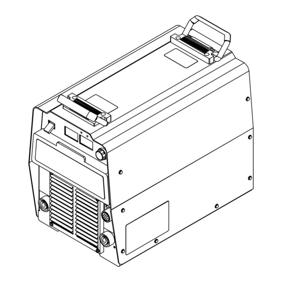
SECTION 4 − INSTALLATION 4-1. Selecting A Location Dimensions And Weight 76 lb (34.6 kg) Movement Location 18 in (460 mm) 24 in (610 mm) 12-1/2 in (318 mm) Do not move or operate unit where it could tip. 18 in (460 mm) 17 in (432 mm) -
Page 18: Weld Output Receptacles And Selecting Cable Sizes
4-2. Weld Output Receptacles And Selecting Cable Sizes ARC WELDING can cause Electromagnetic Interference. To reduce possible interference, keep weld cables as short as possible, close together, and down low, such as on the floor. Locate welding operation 100 meters from any sensitive electronic equipment. Be sure this welding machine is installed and grounded according to this manual. -
Page 19: Remote 14 Receptacle Information
4-3. Remote 14 Receptacle Information C L N C L N *The remaining sockets are not used. 4-4. Optional 115 Volt AC Duplex Receptacle And Circuit Breakers Socket* 24 volts ac. Protected by circuit breaker CB2. 24 VOLTS AC 24 VOLTS AC Contact closure to A completes 24 volts ac contactor control circuit. -
Page 20: Electrical Service Guide
4-5. Electrical Service Guide NOTICE − INCORRECT INPUT POWER can damage this welding power source. This welding power source requires a CONTINUOUS supply of input power at rated frequency(+10%) and voltage (+10%). Phase to ground voltage shall not exceed +10% of rated input voltage. Do not use a genera- tor with automatic idle device (that idles engine when no load is sensed) to supply input power to this welding power source. -
Page 21: Connecting 1-Phase Input Power
4-6. Connecting 1-Phase Input Power Tools Needed: =GND/PE Earth Ground Insulate and isolate red conductor as shown. Connect green grounding conductor to disconnect device grounding terminal first. Connect input conductors L1 and L2 to disconnect device line terminals. 10 Overcurrent Protection Select type and size of overcurrent protection using Section 4-5 (fused disconnect switch shown). -
Page 22: Connecting 3-Phase Input Power
4-7. Connecting 3-Phase Input Power Tools Needed: OM-188 304 Page 18 = GND/PE Earth Ground Installation must meet all National and Local Codes − have only quali- fied persons make this installation. Disconnect and lockout/tagout in- put power before connecting input conductors from unit. -
Page 23: Section 5 − Operation
SECTION 5 − OPERATION 5-1. Front Panel Controls Power Switch The fan motor is thermostatically controlled and only runs when cooling is needed. Voltmeter (see Section 5-2) Ammeter/Trim Indicator (see Section 5-2) Ammeter Light Lights when display beneath is indicating amperage. -
Page 24: Meter Functions
5-2. Meter Functions The meters display the actual weld output values for approximately three seconds after the arc is broken. Mode Preset Volts Pulsed Stick− Contactor Remote Stick− Contactor ON Actual Volts (OCV) Manual Pulse OM-188 304 Page 20 Meter Reading At Idle 24.5 Blank Trim... -
Page 25: Example Displays
5-3. Example Displays The Stick mode provides the Adaptive Hot Start feature, which automatically increases the output amperage at the start of a weld should the start require it. This eliminates electrode sticking at arc start. Values shown are hypothetical. The “A”... -
Page 26: Synergic Controls And Overview
5-4. Synergic Controls And Overview Example To select Program 7, set to Non Adaptive, and set Arc Length to 36, proceed as follows: Select top line by pressing > P r g Select push button until > is on top line. Press Increment button until Program 7 ap- A d a p t i v e pears. -
Page 27: Initial Display, Manual Pulse Mig Mode, Mig Mode, And Stick Mode
5-5. Initial Display, Manual Pulse MIG Mode, MIG Mode, And Stick Mode I N V I S I O N C O P Y R I G H T M I L L E R M f g C o . X X X X X X >... -
Page 28: Setup Screens
5-6. Setup Screens S e t u p A c c e s s i b l e M a n u a l > O f f S e t u p L a n g u a g e >... -
Page 29: Choosing Pulse Programs And Setting Parameters
5-7. Choosing Pulse Programs And Setting Parameters Choosing Pulse Program: Pulse programs are pre-written and cannot be changed by the user. See Section 6 for program parameters and recommended gas mixtures. Choose program depending on the type and size of wire, and type of shielding gas used. -
Page 30: How Manual Pulsed Mig Waveform Components Affect Arc And Burn-Off Rate
5-8. How Manual Pulsed MIG Waveform Components Affect Arc And Burn-Off Rate OM-188 304 Page 26... -
Page 31: Section 6 − Programs
SECTION 6 − PROGRAMS Synergic Information: The manufacturer makes no warranties, express or implied, that welds made using the synergic parameters of this equip- ment will meet the requirements of the application. The synergic parameters contained in this equipment are intended only to be a general guideline. The choice and use of any synergic setting must be tested as to its suitability for the application. - Page 32 Program 2 −− .045 ER70S−3 Mild Steel −− Recommended Gases: Argon/CO Trim Peak Amp Program 3 −− .035 309L Stainless Steel −− Recommended Gases: 98% Argon/2% CO Alternative Gases: Argon/CO Trim Peak Amp Program 4 −− .045 309L Stainless Steel −− Recommended Gases: Argon/CO Trim Peak Amp OM-188 304 Page 28...
- Page 33 Program 5 −− .035 Aluminum 4043 −− Argon Trim Peak Amp Program 6 −− .047 Aluminum 4043 −− Argon Trim Peak Amp Program 7 −− .035 Aluminum 5356 −− Argon Trim Peak Amp Background Amp Freq. Background Amp Freq. Background Amp Freq.
- Page 34 Trim Peak Amp Program 9 −− .035 Nickel −− 75% Argon/25% Helium Trim Peak Amp Trim Peak Amp OM-188 304 Page 30 Program 8 −− .047 Aluminum 5356 −− Argon Background Amp Freq. Background Amp Freq. Program 10 −− .035 Silicon Bronze −− Argon Background Amp Freq.
- Page 35 Program 11 −− .045 Metal Core −− Recommended Gases: Argon/CO Gas: Argon/CO Trim Peak Amp Program 12 −− .052 Metal Core −− Recommended Gases: Argon/CO Gas: Argon/CO Trim Peak Amp mixes up to 20% CO Background Amp Freq. mixes up to 20% CO Background Amp Freq.
-
Page 36: Section 7 − Maintenance & Troubleshooting
SECTION 7 − MAINTENANCE & TROUBLESHOOTING 7-1. Routine Maintenance Replace Damaged Or Unreadable Labels 7-2. Blowing Out Inside Of Unit OM-188 304 Page 32 Disconnect power before maintaining. 3 Months Repair Or Replace Cracked Cables 6 Months Blow Out Inside Maintain more often during severe conditions. -
Page 37: Voltmeter/Ammeter Help Displays
7-3. Voltmeter/Ammeter Help Displays HE.L P−0 HE.L P−1 HE.L P−2 HE.L P−3 HE.L P−4 All directions are in reference to the front of the unit. All circuitry referred to is lo- cated inside the unit. Help 0 Display Indicates a shorted thermistor RT2 on the left side of the unit. -
Page 38: Error Codes
7-4. Error Codes E R R O R P r o g r a m M e m o r y P r e s s E R R O R P r o g r a m M e m o r y P r e s s 7-5. - Page 39 Notes Start Your Professional Over 80,000 trained 400 Trade Square East, Troy, Ohio 45373 Welding Career Now! since 1930! 1-800-332-9448 www.welding.org OM-188 304 Page 35...
-
Page 40: Section 8 − Electrical Diagram
SECTION 8 − ELECTRICAL DIAGRAM 197 556-B Figure 8-1. Circuit Diagram For Welding Power Source (230/460 Volt Models) OM-188 304 Page 36... - Page 41 206 283-A Figure 8-2. Circuit Diagram For Welding Power Source (460/575 Volt Models) OM-188 304 Page 37...
-
Page 42: Section 9 − Parts List
SECTION 9 − PARTS LIST Hardware is common and not available unless listed. 802 166-K Figure 9-1. Parts Assembly OM−188 304 Page 38... - Page 43 Item Dia. Part Mkgs....+175 148 ..... 178 551 .
- Page 44 Item Dia. Part Mkgs... . . +212 210 ... . +208 783 ..PLG13 .
- Page 45 Notes MATERIAL THICKNESS GAUGE...
- Page 46 Notes Work like a Pro! Pros weld and cut safely. Read the safety rules at the beginning of this manual.
- Page 47 Warranty Questions? LIMITED WARRANTY − Subject to the terms and conditions Call below, Miller Electric Mfg. Co., Appleton, Wisconsin, warrants to 1-800-4-A-MILLER its original retail purchaser that new Miller equipment sold after the effective date of this limited warranty is free of defects in for your local material and workmanship at the time it is shipped by Miller.
-
Page 48: Options And Accessories
File a claim for loss or damage during shipment. For assistance in filing or settling claims, contact your distributor and/or equipment manufacturer’s Transportation Department. 2007 Miller Electric Mfg. Co. 2007−01 Miller Electric Mfg. Co. An Illinois Tool Works Company 1635 West Spencer Street Appleton, WI 54914 USA International Headquarters−USA...