Canon L90 Series Service Manual
Hide thumbs
Also See for L90 Series:
- Basic operation manual (214 pages) ,
- Reference manual (193 pages) ,
- Starter manual (28 pages)
Table of Contents
Advertisement
Advertisement
Table of Contents

Related Manuals for Canon L90 Series


Summary of Contents for Canon L90 Series
- Page 1 Service Manual L90/L140/L160/L230 Series FAX-L140 Feb 6 2008...
- Page 3 Canon will release technical information as the need arises. In the event of major changes in the contents of this manual over a long or short period, Canon will issue a new edition of this manual.
- Page 4 Introduction Symbols Used This documentation uses the following symbols to indicate special information: Symbol Description Indicates an item of a non-specific nature, possibly classified as Note, Caution, or Warning. Indicates an item requiring care to avoid electric shocks. Indicates an item requiring care to avoid combustion (fire). Indicates an item prohibiting disassembly to avoid electric shocks or problems.
- Page 5 Introduction The following rules apply throughout this Service Manual: 1. Each chapter contains sections explaining the purpose of specific functions and the relationship between electrical and mechanical systems with refer- ence to the timing of operation. In the diagrams, represents the path of mechanical drive; where a signal name accompanies the symbol , the arrow indicates the direction of the electric signal.
-
Page 7: Table Of Contents
Contents Contents Chapter 1 Introduction 1.1 Product Specifications ..........................1- 1 1.1.1 Names of Parts................................ 1- 1 1.1.1.1 External View ................................... 1- 1 1.1.1.2 Operation Panel ..................................1- 2 1.1.2 Safety ..................................1- 2 1.1.2.1 Safety of Laser Light ................................1- 2 1.1.2.2 Handling the Laser Unit ................................ - Page 8 Contents Chapter 4 Image Formation 4.1 Overview/Configuration ..........................4- 1 4.1.1 Overview ..................................4- 1 4.2 Toner Cartridge ............................4- 1 4.2.1 Display the message...............................4- 1 4.3 Parts Replacement Procedure ........................4- 1 4.3.1 Transfer Charging Roller............................4- 1 4.3.1.1 Removing the Transfer Charging Roller ..........................4- 1 Chapter 5 Pickup and Feed System 5.1 Overview/Configuration ..........................
- Page 9 Contents 6.4.2.2 Removing the Fixing Film Unit ..............................6- 3 6.4.3 Fixing Pressure Roller ............................. 6- 4 6.4.3.1 Preparation for Removing the Fixing Pressure Roller......................6- 4 6.4.3.2 Removing the Fixing Pressure Roller ............................6- 4 Chapter 7 External and Controls 7.1 Power Supply .............................7- 1 7.1.1 Protection Function..............................
- Page 10 Contents 7.2.16.2 Removing the Paper Width Sensor PCB ..........................7- 7 7.2.17 Speaker..................................7- 7 7.2.17.1 Preparation for Removing the Speaker..........................7- 7 7.2.17.2 Removing the Speaker................................7- 7 Chapter 8 Maintenance and Inspection 8.1 Periodically Replaced Parts ........................8- 1 8.1.1 Periodic Replacement Parts ............................8- 1 8.2 Consumables .............................
- Page 11 Contents 12.3.3.1 List of Functions ................................. 12- 11 12.3.3.2 Details of Bit 1 ..................................12- 11 12.3.3.3 Details of Bit 2 ..................................12- 11 12.3.4 SSSW-SW16 ..............................12- 11 12.3.4.1 List of Functions ................................. 12- 11 12.3.4.2 Details of Bit 3 ..................................12- 12 12.3.5 SSSW-SW30 ..............................
- Page 12 Contents...
-
Page 13: Chapter 1 Introduction
Chapter 1 Introduction... - Page 15 Contents Contents 1.1 Product Specifications..............................1-1 1.1.1 Names of Parts ..................................... 1-1 1.1.1.1 External View........................................1-1 1.1.1.2 Operation Panel.......................................1-2 1.1.2 Safety ......................................1-2 1.1.2.1 Safety of Laser Light.......................................1-2 1.1.2.2 Handling the Laser Unit ....................................1-3 1.1.2.3 Safety of Toner........................................1-3 1.1.2.4 Point to Note about Fire ....................................1-3 1.1.2.5 Point to Note about Battery Replacement ...............................1-3 1.1.3 Function List ....................................
-
Page 17: Product Specifications
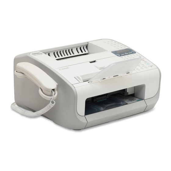
Chapter 1 1.1 Product Specifications 1.1.1 Names of Parts 1.1.1.1 External View 0018-4889 Front F-1-1 T-1-1 [A] Paper delivery tray [H] Automatic document feeder (ADF) [B] Paper delivery tray extension [I] Document feeder tray [C] Cartridge cover [J] Document feeder tray extention [D] Notch [K] Document delivery tray [E] Operation panel... -
Page 18: Operation Panel
Chapter 1 T-1-2 [N] Handset (Optional) [R] External device jack [O] Handset cradle (Optional) [S] Line jack [P] USB port [T] Handset cable retainer(Optional) [Q] Handset jack [U] Power socket 1.1.1.2 Operation Panel 0018-4891 F-1-3 T-1-3 [A] One-touch speed dialing button [K] Hook button [B] LCD [L] Numeric buttons... -
Page 19: Handling The Laser Unit
Chapter 1 1.1.2.2 Handling the Laser Unit 0018-4894 The laser scanner unit emits invisible laser light inside it. If exposed to laser light, the human eye can irreparably be damaged. Never attempt to disassemble the laser scanner unit. (It is not designed for servicing in the field). The covers around the laser scanner unit are identified by the following label [1]. -
Page 20: Function List
Chapter 1 1.1.3 Function List 1.1.3.1 Scanning Range (Transmission) 0018-4882 [10] F-1-5 T-1-4 [1] Document leading edge [6] Effective scanning length [2] Left margin [7] Bottom margin [3] Effective scanning width [8] Scanning drop out range [4] Right margin [9] Scanning range [5] Top margin [10] Document trailing edge T-1-5... -
Page 21: Printing Range (Printer)
Chapter 1 T-1-6 [1] Paper leading edge [6] Effective printing length [2] Left margin [7] Bottom margin [3] Effective printing width [8] Printing drop out range [4] Right margin [9] Printing range [5] Top margin [10] Paper trailing edge T-1-7 Item Letter Legal... - Page 22 Chapter 1 Computer Any computer on whitch Windows 98/98SE, Windows Me, Windows 2000, or Windows XP runs properly. T-1-10 Available Free Disk Space 24 MB of RAM or Intel 80486DX 66 MHz or At least 355MB or greater is Windows 98/98SE greater is greater recommended...
-
Page 23: Chapter 2 Document Feed And Exposure System
Chapter 2 Document Feed and Exposure System... - Page 25 Contents Contents 2.1 Overview/Configuration ..............................2-1 2.1.1 Overview...................................... 2-1 2.2 Parts Replacement Procedure............................2-1 2.2.1 Separation Guide Unit.................................. 2-1 2.2.1.1 Preparation for Removing the Scraper ................................2-1 2.2.1.2 Removing the Scraper .....................................2-1 2.2.2 Contact Sensor ..................................... 2-2 2.2.2.1 Preparation for Removing the Contact Sensor..............................2-2 2.2.2.2 Removing the Contact Sensor..................................2-2 2.2.3 Separation Roller ..................................
-
Page 27: Overview/Configuration
Chapter 2 2.1 Overview/Configuration T-2-1 2.1.1 Overview 0018-4898 F-2-1 [1] Separation guide [4] Contact sensor [2] Separation roller [5] Document delivery roller [3] Document feed roller 2.2.1.2 Removing the Scraper 0018-4168 1) Free the claw [1], and detach the upper reader unit frame [2]. Reading from the ADF To avoid skew feeding, documents loaded on the document tray are retained in the horizontal direction by the slide guide. -
Page 28: Contact Sensor
Chapter 2 F-2-7 F-2-4 2.2.2 Contact Sensor 2.2.2.1 Preparation for Removing the Contact Sensor 0018-4169 1) Remove the document feed tray and the paper tray cover. (page 7-2)Ref- erence[Removing the Document Feed Tray and the Paper Tray Cover] 2) Detach the right cover. (page 7-2)Reference[Detaching the Right Cov- 3) Detach the left cover. -
Page 29: Separation Roller
Chapter 2 5) Detach the contact sensor [1] from the lower reader unit frame, and dis- connect the connector [2]. F-2-8 2.2.3 Separation Roller 2.2.3.1 Preparation for Removing the Document Separation Roller 0018-4171 1) Remove the document feed tray and the paper tray cover. (page 7-2)Ref- erence[Removing the Document Feed Tray and the Paper Tray Cover] 2) Detach the right cover. -
Page 30: Feed Roller
Chapter 2 6) Remove the E-ring [1], and detach the separation roller [2] from the shaft. F-2-11 2.2.4 Feed Roller 2.2.4.1 Preparation for Removing the Document Feed Roller 0018-4173 1) Remove the document feed tray and the paper tray cover. (page 7-2)Ref- erence[Removing the Document Feed Tray and the Paper Tray Cover] 2) Detach the right cover. -
Page 31: Reader Unit
Chapter 2 6) Detach the cartridge cover. (page 7-3)Reference[Detaching the Car- 4) Remove the 6 gears [1]. tridge Cover] 7) Remove the control panel unit. (page 7-4)Rference[Removing the Con- trol Panel Unit] 8) Detach the upper cover. (page 7-3)Reference[Detaching the Upper Cov- 2.2.5.2 Removing the Reader Unit 0018-3975 1) Remove the clamp [1]. -
Page 32: Ds/Des Sensor
Chapter 2 F-2-22 5) Remove the 7 screws [1], and detach the cover [2]. F-2-19 2.2.7 DS/DES Sensor 2.2.7.1 Preparation for Removing the DS/DES Sensor 0018-4177 1) Remove the document feed tray and the paper tray cover. (page 7-2)Ref- erence[Removing the Document Feed Tray and the Paper Tray Cover] 2) Detach the right cover. -
Page 33: Chapter 3 Laser Exposure
Chapter 3 Laser Exposure... - Page 35 Contents Contents 3.1 Overview/Configuration ..............................3-1 3.1.1 Overview...................................... 3-1 3.2 Parts Replacement Procedure............................3-1 3.2.1 Laser/Scanner Unit..................................3-1 3.2.1.1 Preparation for Removing the Laser/Scanner Unit ............................3-1 3.2.1.2 Removing the Laser/Scanner Unit ..................................3-1...
-
Page 37: Overview/Configuration
Chapter 3 3.1 Overview/Configuration T-3-1 3.1.1 Overview 0018-4899 F-3-1 [1] Laser driver PCB [5] Scanner motor [2] BD sensor [6] 4-facet mirror [3] Photosensitive drum [7] Cylindrical lens [4] Imaging lends 3.2 Parts Replacement Procedure The machine's laser scanner assembly consists of the laser driver and the 3.2.1 Laser/Scanner Unit scanner motor, which are driven by signals coming from the DCNT board. -
Page 39: Chapter 4 Image Formation
Chapter 4 Image Formation... - Page 41 Contents Contents 4.1 Overview/Configuration ..............................4-1 4.1.1 Overview...................................... 4-1 4.2 Toner Cartridge ................................4-1 4.2.1 Display the message..................................4-1 4.3 Parts Replacement Procedure............................4-1 4.3.1 Transfer Charging Roller ................................4-1 4.3.1.1 Removing the Transfer Charging Roller.................................4-1...
-
Page 43: Overview/Configuration
Chapter 4 4.1 Overview/Configuration T-4-1 4.1.1 Overview 0018-4900 F-4-1 [1] Laser/scanner assembly [5] Photosensitive drum [2] Laser beam [6] Transfer charging roller [3] Blade [7] Primary charging roller [4] Developing cylinder [8] Cleaning blade 4.3 Parts Replacement Procedure In response to a print command, the DCNT board turns on the main motor to drive the photosensitive drum, developing cylinder, primary charging roller, and transfer charging roller. -
Page 45: Chapter 5 Pickup And Feed System
Chapter 5 Pickup and Feed System... - Page 47 Contents Contents 5.1 Overview/Configuration ..............................5-1 5.1.1 Overview...................................... 5-1 5.2 Detection Jams ................................5-1 5.2.1 Jam Detection Outline.................................. 5-1 5.2.1.1 Type of Jams ........................................5-1 5.2.2 Delay Jams ....................................5-2 5.2.2.1 Pickup Delay Jam......................................5-2 5.2.2.2 Delivery Delay Jam......................................5-2 5.2.3 Stationary Jams .................................... 5-2 5.2.3.1 Pickup Stationary Jam.....................................5-2 5.2.3.2 Delivery Stationary Jam ....................................5-2 5.2.4 Other Jams ....................................
-
Page 49: Overview/Configuration
Chapter 5 5.1 Overview/Configuration 5.1.1 Overview 0018-4902 PS803 PS804 PS801 PS802 F-5-1 T-5-1 [1] Face-down delivery roller [8] Toner sensor [2] Fixing pressure roller [PS801] Paper leading edge sensor [3] Transfer charging roller [PS802] Paper width sensor [4] Separation pad [PS803] Delivery sensor [5] Pickup roller [PS804] Paper width 2 sensor... -
Page 50: Delay Jams
Chapter 5 Delivery Stationary Jam tridge Cover] 6) Remove the control panel unit. (page 7-4)Rference[Removing the Con- The paper leading edge sensor goes off, but the delivery sensor does not go on within a specific period of time. trol Panel Unit] Wrap Jam The delivery sensor goes on, but it goes off before a specific period of 5.3.1.2 Removing the Paper Pickup Unit... -
Page 51: Cassette Pickup Roller
Chapter 5 F-5-5 5.3.2 Cassette Pickup Roller 5.3.2.1 Removing the Cassette Pickup Roller F-5-8 0018-4187 1) Open the document feeder tray. 7) Remove the 4 screws [1], and detach the gear side plate [2]. 2) Open the cartridge cover. 3) While pushing the 2 claws [1] outward, detach the pickup roller [2]. F-5-6 5.3.3 Cassette Pickup Solenoid F-5-9... -
Page 52: Main Motor
Chapter 5 5.3.5 Main Motor 5.3.5.1 Preparation for Removing the Main Motor 0018-4192 1) Remove the document feed tray and the paper tray cover. (page 7-2)Ref- erence[Removing the Document Feed Tray and the Paper Tray Cover] 2) Detach the right cover. (page 7-2)Reference[Detaching the Right Cov- 3) Detach the left cover. -
Page 53: Chapter 6 Fixing System
Chapter 6 Fixing System... - Page 55 Contents Contents 6.1 Overview/Configuration ..............................6-1 6.1.1 Overview...................................... 6-1 6.2 Various Control Mechanisms............................6-1 6.2.1 Controlling the Temperature of the Fixing Unit .......................... 6-1 6.2.1.1 Heater Temperature Control ...................................6-1 6.3 Protection Function ................................6-3 6.3.1 Protective Mechanisms ................................6-3 6.3.2 Detection of a Fault..................................6-3 6.4 Parts Replacement Procedure............................6-3 6.4.1 Fixing Unit ....................................
-
Page 57: Overview/Configuration
Chapter 6 6.1 Overview/Configuration 6.1.1 Overview 0018-4912 PS803 F-6-1 T-6-1 [1] Fixing film unit [PS803] Delivery sensor [2] Pressure roller [M1] Main motor [3] Face-down delivery roller The machine's fixing system is an on-demand type, and its fixing assembly consists of the fixing film unit: the fixing film has a built-in fixing heater, thermistor, and thermal fuse. - Page 58 Chapter 6 Power supply PCB DCNT board FSRD Fixing control circuit J201-19 J902-5 Fixing heater safety circuit Fuse (FU101) +24V +3.3V Relay (RL101) SSR101 IC902 +24V Q102 Q103 FSRTH IC501 Fixing heater drive circuit J201-20 J902-4 J303-3 J303-1 Q104 Thermistor (TH1) Fixing film unit RLYD J302-4...
-
Page 59: Protection Function
Chapter 6 6.4.1.2 Removing the Fixing Unit 0018-4197 1) Disconnect the 5 connectors [1]. The term "long narrow paper" refers to a type of paper that is narrow in width 2) Free the harness [3] from the cable guide [2]. and long in length. -
Page 60: Fixing Pressure Roller
Chapter 6 F-6-6 2) Remove the 2 screws [1], and detach the fixing cover [2]. F-6-9 F-6-7 3) Remove the 2 springs [1], and detach the 2 releasing levers [2]. 4) Remove the 2 locking plate [3], and detach the fixing film unit [4]. F-6-8 6.4.3 Fixing Pressure Roller 6.4.3.1 Preparation for Removing the Fixing Pressure... -
Page 61: Chapter 7 External And Controls
Chapter 7 External and Controls... - Page 63 Contents Contents 7.1 Power Supply .................................7-1 7.1.1 Protection Function ..................................7-1 7.1.1.1 Protective Mechanisms ....................................7-1 7.1.2 Backup Battery..................................... 7-1 7.1.2.1 Battery-backed up Data....................................7-1 7.2 Parts Replacement Procedure............................7-1 7.2.1 Front Cover ....................................7-1 7.2.1.1 Preparation for Detaching the Front Cover ..............................7-1 7.2.1.2 Detaching the Front Cover ....................................7-1 7.2.2 Rear Cover ....................................
- Page 64 Contents 7.2.17 Speaker....................................... 7-7 7.2.17.1 Preparation for Removing the Speaker ................................. 7-7 7.2.17.2 Removing the Speaker ....................................7-7...
-
Page 65: Power Supply
Chapter 7 7.1 Power Supply 7.2.2 Rear Cover 7.2.2.1 Preparation for Detaching the Rear Cover 7.1.1 Protection Function 0018-3915 1) Remove the document feed tray and the paper tray cover. (page 7-2)Ref- erence[Removing the Document Feed Tray and the Paper Tray Cover] 7.1.1.1 Protective Mechanisms 2) Detach the right cover. -
Page 66: Right Cover
Chapter 7 3) Push the left of the rear cover [1] in the arrow [A] direction to disengage the claw [2] from the receptacle hole [3]. 4) Insert a screwdriver etc into the indicated hole [4] by approx 10mm in the horizontal direction and push the claw in the arrow [B] direction to disen- gage the claw [5] from the receptacle hole [6]. -
Page 67: Upper Cover
Chapter 7 F-7-7 F-7-9 7.2.6 Upper Cover 7.2.6.1 Preparation for Detaching the Upper Cover 0018-3960 1) Remove the document feed tray and the paper tray cover. (page 7-2)Ref- erence[Removing the Document Feed Tray and the Paper Tray Cover] 2) Detach the right cover. (page 7-2)Reference[Detaching the Right Cov- 3) Detach the left cover. -
Page 68: Operation Panel Unit
Chapter 7 2) Remove the 6 screws [3], and detach the SCNT board [4]. When mounting the cartridge cover, be sure to fit the 2 fixing assembly release hooks [2] in the 2 hook holes [1] found in the cartridge cover. F-7-11 Bad position Good position... -
Page 69: High-Voitage Power Supply Pcb
Chapter 7 F-7-13 4) Remove the clamp [1] and disconnect the 2 flat cables [2]. 5) Free the harness [4] from the guide [3]. 6) Remove the screw [5] and turn the DCNT board [6] upside down. F-7-15 7.2.11 High-voitage Power Supply PCB 7.2.11.1 Preparation for Removing the High-Voltage Power Supply Board 0018-4153... -
Page 70: Powwer Supply Pcb
Chapter 7 F-7-19 7.2.14 Paper Delivery Sensor 7.2.14.1 Preparation for Removing the Paper Delivery F-7-17 Sensor PCB 0018-4157 1) Remove the document feed tray and the paper tray cover. (page 7-2)Ref- 7.2.12 Powwer Supply PCB erence[Removing the Document Feed Tray and the Paper Tray Cover] 2) Detach the right cover. -
Page 71: Removing The Toner Sensor
Chapter 7 7.2.15.2 Removing the Toner Sensor 0018-4162 1) Remove the clamp [1] and disconnect the connector [2]. F-7-25 7.2.17 Speaker F-7-22 7.2.17.1 Preparation for Removing the Speaker 2) Open the toner sensor [1]. 0018-4165 1) Remove the document feed tray and the paper tray cover. (page 7-2)Ref- erence[Removing the Document Feed Tray and the Paper Tray Cover] 2) Detach the right cover. -
Page 73: Chapter 8 Maintenance And Inspection
Chapter 8 Maintenance and Inspection... - Page 75 Contents Contents 8.1 Periodically Replaced Parts ............................8-1 8.1.1 Periodic Replacement Parts ................................. 8-1 8.2 Consumables ..................................8-1 8.2.1 Consumable....................................8-1 8.3 Periodical Service ................................8-1 8.3.1 Scheduled service Parts................................8-1 8.4 Cleaning ..................................8-1 8.4.1 Items Requiring Cleaning ................................8-1 8.4.2 Cleaning Method (external covers).............................. 8-2 8.4.3 Cleaning Method (scanning unit)..............................
-
Page 77: Periodically Replaced Parts
Chapter 8 8.1 Periodically Replaced Parts 8.1.1 Periodic Replacement Parts 0018-4922 - No parts require periodic replacement in this printer. 8.2 Consumables 8.2.1 Consumable 0018-4924 T-8-1 Work by Item Interval (guide) User Cartridge FX-9S When toner in the toner cartridge being used has run out. -
Page 78: Cleaning Method (External Covers)
Chapter 8 Work by Item Intervals Fixing entrance guide When paper tends to become soiled; when a black line appears vertically at irregular intervals; when paper jams; when paper wrinkles - Be sure to disconnect the power plug hefore starting the cleaning work. The machine must remain without power to avoid fire hazards and electric shocks. 8.4.2 Cleaning Method (external covers) 0018-4930 Moisten a soft cloth with water or solution of mild detergent, making sure it is well wrung;... -
Page 79: Cleaning (Printer Unit)
Chapter 8 8.4.4 Cleaning (printer unit) 0018-4933 F-8-2 Be sure to follow the instructions given below when cleaning the components as part of service work: [1] Transfer Charging Roller As a rule, do not touch or clean the part. If absolutely necessary, be sure to take full care not to touch the roller and bring solvent or oil into contact with the roller. Cleaning must be dry-wiping with lint-free paper. -
Page 81: Chapter 9 Measurement And Adjustments
Chapter 9 Measurement and Adjustments... - Page 83 Contents Contents 9.1 Image Adjustments ................................9-1 9.1.1 Adjusting the Paper Margin ................................. 9-1 9.1.2 Read Adjustment..................................9-1 9.1.3 Print Adjustment ..................................9-1...
-
Page 85: Image Adjustments
Chapter 9 9.1 Image Adjustments Setting value Contents 99.2% 9.1.1 Adjusting the Paper Margin 0018-4998 Press the menu button and then the # button to select SERVICE MODE; 99.6% then, using the cursor button, select SERVICE'S CHOICE, and press the OK button. - Page 86 Chapter 9 T-9-5 MAIN Regist Setting value Contents -10 (-5.0 mm) -9 (-4.5 mm) -8 (-4.0 mm) -7 (-3.5 mm) -6 (-3.0 mm) -5 (-2.5 mm) -4 (-2.0 mm) -3 (-1.5 mm) F-9-3 -2 (-1.0 mm) -1 (-0.5 mm) T-9-4 Setting value Contents -10 (-5.0 mm)
-
Page 87: Chapter 10 Correcting Faulty Images
Chapter 10 Correcting Faulty Images... - Page 89 Contents Contents 10.1 Troubleshooting .................................10-1 10.1.1 Phenomenon Table................................... 10-1 10.1.1.1 Symptoms........................................10-1 10.2 Outline of Electrical Components..........................10-1 10.2.1 Sensor....................................... 10-1 10.2.1.1 Arrangement of Sensors and Switches................................10-1 10.2.2 PCBs ......................................10-2 10.2.2.1 Arrangement of PCBs ....................................10-2...
-
Page 91: Troubleshooting
Chapter 10 10.1 Troubleshooting 10.1.1 Phenomenon Table 10.1.1.1 Symptoms 0018-5004 T-10-1 Level 1 Symptom Image Faults Image Faults Occurring at Specific Intervals Initial Offset in a Low Temperature/Humidity Environment Black Lines Caused by Drum Memory Malfunction The Session No. of Activiry report is reset each time the power is turned off and then back on. -
Page 92: Pcbs
Chapter 10 10.2.2 PCBs 10.2.2.1 Arrangement of PCBs 0018-4210 F-10-2 [1] High-Voltage Power Supply Board [2] Power Supply Board [3] DCNT Board [4] SCNT Board 10-2... -
Page 93: Error Code
Chapter 11 Error Code... - Page 95 Contents Contents 11.1 Error Code..................................11-1 11.1.1 Error Code....................................11-1...
-
Page 97: Error Code
Chapter 11 11.1 Error Code 11.1.1 Error Code 0018-5043 System error code T-11-1 Error Major cause/detection Remedy code E198 Flash ROM write error. - Turn the power OFF and then back ON.. - Replace the SCNT board. E674 Modem error. - Turn the power OFF and then back ON.. - Page 98 Chapter 11 Error Code Description 0040 Can't receive carrier within 6 sec. after sending CTR signal. 0041 Can't receive carrier within 6 sec. after sending PPR signal. 0042 Can't receive correct signal after sending RNR signal 0043 Fault occurred in the communication procedure signal 0044 Can't receive carrier /FSK signal within 6 sec.
- Page 99 Chapter 11 Error Code Description Cannot finish V8 procedure or detect V21 signal after ANSam signal within 00B1 35sec 00B2 Can't detect phase 2 signal after our side sending CJ signal within 30 sec 00B3 Can't detect correct V21 or JM signal after sending CM signal Can't detect correct phase 2 signal within 25 seconds after CM/JM signal 00B4 exchange...
-
Page 101: Chapter 12 Service Mode
Chapter 12 Service Mode... - Page 103 Contents Contents 12.1 Outline..................................12-1 12.1.1 Service Data Setting................................. 12-1 12.1.2 Service Data Entry Method..............................12-1 12.1.3 Service Data menu ................................... 12-2 12.2 Default Settings................................12-3 12.2.1 SSSW Default Settings ................................12-3 12.3 Service Soft Switch Settings (SSSW) ........................12-10 12.3.1 Outline....................................12-10 12.3.1.1 Explanation of SOFT SWITCH ................................12-10 12.3.2 SSSW-SW02:..................................
-
Page 105: Outline
Chapter 12 12.1 Outline 12.1.1 Service Data Setting 0018-5009 Service mode has the following service data items. These items can be checked/changed according to the menu on the display. SERVICE'S CHOICE Use it to select service data to suit the country/region of installation, to reset the user data, or to set the transmission/reception speed. ADJUST Use it to execute margin adjustment for printing or reading. -
Page 106: Service Data Menu
Chapter 12 12.1.3 Service Data menu 0018-5011 Service menu SERVICE CHOISE COUNTRY/REGION HUNGARY CODE SWEDEN KOREA SWITZERLAND CHINA AUSTRIA GERMAN DENMARK FRANCE NORWAY SINGAPORE HOLLAND CZECH BELGIUM SLOVENIA AUSTRALIA CANADA FINLAND RUSSIA ASIA ITALY POLAND SPAIN EUROPE2 PORTUGAL LUXEMBOURG IRELAND GREECE HONG KONG TAIWAN... -
Page 107: Default Settings
Chapter 12 1 2 3 4 5 6 7 8 SOFT SWITCH SW01 - - - - - - - - Not used SW02 - 0 0 - - - - - SW03 SW06: Not used SW07 - - - - - - - 0 SW08 - - - - - - - - Not used... - Page 108 Chapter 12 SWITZERLAN TYPE U.K. SWEDEN AUSTRIA DENMARK SW05 00000011 00000011 00001011 10000011 10000011 00000011 SW06 00000000 00000000 00000000 00000000 00000000 00000000 SW07 10100000 10100000 10100000 10100000 10100000 10100000 SW08 00000100 00000100 00000110 00000110 00000110 00000110 SW09 00000000 00000000 00000000 00000000 00000000 00000000...
- Page 109 Chapter 12 T-12-2 TYPE NORWAY HOLLAND BELGIUM AUSTRALIA FINLAND N.Z. SOFT SWITCH SW01 00000000 00000000 00000000 00000000 00000000 00000000 SW02 00000100 00000100 00000100 00000100 00000100 00000100 SW03 00001000 00001000 00000000 00001000 00001000 00001000 SW04 00000000 00000000 00000000 00000000 00000000 00000000 SW05 00000111 00000011...
- Page 110 Chapter 12 TYPE NORWAY HOLLAND BELGIUM AUSTRALIA FINLAND N.Z. SW64 00000000 00000000 00000000 00000000 00000000 00000000 T-12-3 TYPE ITALY SPAIN PORTUGAL IRELAND HONGKONG MALAYSIA SOFT SWITCH SW01 00000000 00000000 00000000 00000000 00000000 00000000 SW02 00000100 00000100 00000100 00000100 00000100 00000100 SW03 00001000 00001000...
- Page 111 Chapter 12 TYPE ITALY SPAIN PORTUGAL IRELAND HONGKONG MALAYSIA SW60 00000000 00000000 00000000 00000000 00000000 00000000 SW61 11110000 11110000 11110000 11110000 11110000 11110000 SW62 00000000 00000000 00000000 00000000 00000000 00000000 SW63 00000000 00000000 00000000 00000000 00000000 00000000 SW64 00000000 00000000 00000000 00000000 00000000...
- Page 112 Chapter 12 TYPE HUNGARY KOREA CHINA GERMAN FRANCE SW56 00000000 00000000 00000000 00000000 00000000 00000000 SW57 00000000 00000000 00000000 00000000 00000000 00000000 SW58 00000000 00000000 00000000 00000000 00000000 00000000 SW59 00000000 00000000 00000000 00000000 00000000 00000000 SW60 00000000 00000000 00000000 00000000 00000000 00000000...
- Page 113 Chapter 12 TYPE SINGAPORE CZECH SLOVENIA RUSSIA ASIA POLAND SW52 10000011 10000011 10000011 10000011 10000011 10000011 SW53 10000011 10000011 10000011 10000011 10000011 10000011 SW54 00000011 00000011 00000001 00000011 00000011 00000011 SW55 00000000 00000000 00000000 00000000 00000000 00000000 SW56 00000000 00000000 00000000 00000000 00000000...
-
Page 114: Service Soft Switch Settings (Sssw)
Chapter 12 LUXEMBOU TYPE EUROPE2 GREECE TAIWAN OTHERS SW47 00000000 00000000 00000000 00000000 00000000 SW48 00100101 00100101 00100101 00100101 00100101 SW49 10001000 10001000 10001000 10001000 10001000 SW50 00000000 00000000 00000000 00000000 00000000 SW51 00000000 00000000 00000000 00000000 00000000 SW52 10000011 10000011 10000011 10000011... -
Page 115: Sssw-Sw10
Chapter 12 Function RTN signal transmission condition Not used Not used Not used Not used Not used 12.3.2.2 Details of Bit 2 and Bit 3 0018-5015 During reception if frequent errors occur because of RTN signal transmission, raise these parameters to loosen the RTN signal transmission conditions. RTN signal transmission condition is the ratio of the number of error lines to the total number of lines per page of the received image. -
Page 116: Sssw-Sw30
Chapter 12 Function Not used Not used Not used Not used Not used 12.3.4.2 Details of Bit 3 0018-5923 The document reading width can be selected. When selecting the "LTR" size, a "LTR" size document can be read in the "LTR"... -
Page 117: Details Of Bit 1 Through Bit 6
Chapter 12 Function Not used Not used 12.3.6.2 Details of Bit 1 through Bit 6 0018-5027 Select the maximum baud rate for V.34 transmission: 3429, 3200, 3000, 2800, and 2400. The following will be ture depending on the combination of bit 1 through bit 6 at time of transmission T-12-14 (Bit1, Bit2, Bit3)= (0, 0, 0) 3429... -
Page 118: Sssw-Sw54
Chapter 12 (1, 1) Not used 12.3.8 SSSW-SW54 12.3.8.1 List of Functions 0018-5925 T-12-18 Function Not used Not used Not used Not used Not used Date/time notation for report Date/time notation for report Month notation for report 12.3.8.2 Details of Bit 6 and Bit 7 0018-5031 Use it to select the date/time notation for reports;... -
Page 119: Report Output (Report)
Chapter 12 12.4 Report Output (REPORT) 12.4.1 SERVICE DATA LIST 0018-5033 SERVICE DATA LIST N A M E : T E L D AT E : 0 8 . A P R . 2 0 0 5 1 8 : 1 5 C O U N T R Y C O D E = U K S O F T S W I T C H S W 0 1 - S W 1 6... -
Page 120: Adf Feed Test
Chapter 12 Use the BLACK print pattern to meke sure that the printout is free of white lines and unevenness; on the other hand, use the SQUARE printout to make sure that the printout is free of image contraction, elongation, and soiling. Memo After completion of the print test, if the printing was normal, copy a document. -
Page 121: Service Tools
Chapter 13 Service Tools... - Page 123 Contents Contents 13.1 Service Tools................................13-1 13.1.1 Solvent/Oil List ..................................13-1...
-
Page 125: Solvent/Oil List
Chapter 13 13.1 Service Tools 13.1.1 Solvent/Oil List 0018-5007 T-13-1 Name Components Remarks Alcohol Cleaning:plastic Alcohol -Flammable:keep away from flame (note),rubber,metal,oil,and -Purchase locally toner stains Lubricant Apply to gears, between shaft Special oil Special -Tool No. HY9-0007 and bushing solid lubricating material Lithium soap Lubricant... - Page 127 Feb 6 2008...