Sign In
Upload
Manuals
Brands
York Manuals
Air Conditioner
ZF SERIES
York ZF SERIES Manuals
Manuals and User Guides for York ZF SERIES. We have
8
York ZF SERIES manuals available for free PDF download: Technical Manual, Wiring Diagrams, Instruction Manual, Installation Manual
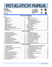
York ZF SERIES Installation Manual (71 pages)
Brand:
York
| Category:
Air Conditioner
| Size: 3.74 MB
Table of Contents
Table of Contents
1
General
3
Installation
7
Installation Safety Information
7
Limitations
7
Location
7
Rigging and Handling
8
Condensate Drain
9
Compressors
9
Filters
9
Service Access
9
Typical Cool/Heat Control Wiring
11
Thermostat
11
Power and Control Wiring
11
Optional Electric Heat
12
Control Wire Sizes
12
Optional Gas Heat
13
Gas Piping
13
Gas Connection
13
Electric Heater Supply Air Limitations
13
Gas Heat Application Data
13
Gas Pipe Sizing
13
L.P. Units, Tanks, and Piping
14
Vent and Combustion Air Hoods
15
VENT and Combustion Air Hood
15
RRS Economizer Interface Overview
16
Smart Equipment™ Economizer Sequences
16
Dry Bulb Changeover
17
Single Enthalpy Changeover
17
Dual Enthalpy Changeover
17
Auto
17
Free Cooling Operation
17
Power Exhaust
18
Operation
18
Smart Equipment™ Economizer Board Details
19
Jade Economizer Interface Overview
22
Single Enthalpy Curve and Boundaries
23
Single Enthalpy and Dual Enthalpy High Limit Curves
24
ZF036-076 Unit Weights
25
ZF036-076 Imperial
25
ZF036-076 Metric
25
ZF036-076 Unit Accessory Weights
25
ZF036-076 Physical Data
26
Electrical Data ZF036-076
28
Electric Heat Correction Factors
28
Voltage Limitations
28
Unit Dimensions (3 - 6.3 Ton Cooling Only/Electric Heat) Front
29
Unit Dimension (3 - 6.3 Ton Cooling/Gas Heat) Front View
29
Unit with Fixed Outdoor Air/Motorized Damper Rain Hood
30
Utilities Entry
31
Minimum Clearances
31
Unit Dimensions (Rear View)
31
Supply Air Blower Performance (3 and 4 Ton Direct Drive) - Side Duct Applications
32
Supply Air Blower Performance (5 Ton Belt Drive) - Side Duct Application
33
Supply Air Blower Performance (6.3 Ton Belt Drive) - Side Duct
34
Application
34
Phasing
35
Supply Air Blowers
35
Checking Supply Airflow Rate
35
Belt Drive Motor and Drive Data
35
Static Resistances
35
Belt Adjustment
36
Operation
37
Cooling Sequence of Operation
37
Electric Heating Sequence of Operations
39
Safety Controls
39
Heat Anticipator Setpoints
40
Gas Heating Sequence of Operation
40
Gas Heat Operation Errors
40
Limit Control Setting
40
Electric Heat Anticipator Setpoints
40
Flash Codes or Error Messages
41
Heat Anticipator Setpoints
41
Limit Control Setting
41
Gas Heat Anticipator Setpoints
41
Start-Up (Cooling)
42
Prestart Checklist
42
Operating Instructions
42
Post Start Checklist
42
Shutting down the Unit
42
Start up (Gas Heat)
42
Post Start Checklist (Gas)
42
Manifold Gas Pressure Adjustment
43
Pilot Checkout
43
Burner Instructions
43
Burner Air Shutter Adjustment
43
Checking Gas Input
43
Typical Valves
43
Adjustment of Temperature Rise
44
Gas Rate - Cubic Feet Per Hour
44
Troubleshooting
45
Cooling Troubleshooting Guide
45
Gas Heat Troubleshooting Guide
46
Flash Code Troubleshooting
47
Symptomatic Troubleshooting
49
Unit Flash Codes
50
Fan on and off Delays
50
Navigation Components for the Smart Equipment™ Control
51
Board
51
Simplicity Lite Unit Control Board Flash Codes
51
Ignition Control Board Flash Codes
51
Simplicity Lite Unit Control Board
51
Smart Equipment™ UCB Details
52
Smart Equipment™ Unit Control Board
52
Typical Wiring Diagrams
58
Simplicity® Lite Control Board
58
Typical ZF036, 048 with Simplicity Lite Control, With/Without Electric Heat Wiring Diagram
58
Typical ZF036, 048 with Simplicity Lite Control, with Gas
59
Typical ZF060, 076 with Simplicity Lite Control, With/Without Electric Heat Wiring Diagram
60
Typical ZF060, 076 with Simplicity Lite Control, with Gas
61
Smart Equipment
62
Typical ZF036, 048 with Smart Equipment™ Control, with
62
Typical ZF036, 048 with Smart Equipment™ Control, with
63
Typical ZF060, 076 with Smart Equipment™ Control, with
64
Typical ZF060, 076 with Smart Equipment™ Control, with
65
Start-Up Sheet
66
5725848-XIM-A-0319
71
Advertisement
York ZF SERIES Instruction Manual (75 pages)
Brand:
York
| Category:
Air Conditioner
| Size: 2.63 MB
Table of Contents
Table of Contents
1
General
2
Installation
5
Preceding Installation
5
Unit Shipping Bracket
5
Condenser Covering
5
Compressor Section
5
Limitations
6
Predator ® Component Location (ZF120 Shown)
6
Location
7
Rigging and Handling
7
ZF078-150 Unit Limitations
7
Weights and Dimensions
8
Unit 4 Point Load Weight
8
Unit 6 Point Load Weight
8
Center of Gravity
8
ZF078-150 Unit Accessory Weights
9
Zf078-120
9
Zf150
10
ZF078-150 Unit Physical Dimensions
11
ZF078-150 Unit Clearances
11
ZF078-150 Unit Bottom Duct Openings
12
ZF078-150 Unit Electrical Entry
13
ZF078-120 Unit Side Duct Openings
13
Side Duct Dimensions
14
Left/End Duct Dimensions
14
ZF150 Unit Side Duct Openings
14
ZF078-150 Unit Left Duct Opening
14
Ductwork
15
ZF078-150 Roof Curb
15
ZF078-150 Transition Roof Curb
15
Side Panels
16
Condensate Drain
16
Side Panels with Hole Plugs
16
Return Downflow Plenum with Panel
16
Discharge Panel in Place
16
Save Side Panels for Economizer Hood Tops
16
Compressors
17
Filters
17
Power and Control Wiring
17
Condensate Drain
17
Field Wiring Disconnect - Cooling Unit With/Without Electric Heat and All Units with VFD Option
18
Field Wiring Disconnect - Cooling Unit with Gas Heat Without VFD Option
19
Control Wire Sizes
20
Typical Electronic Thermostat Field Wiring
20
Electrical Data
21
ZF078-150 Physical Data
29
Optional Electric Heat
31
Electric Heat Minimum Supply Air
31
Optional Gas Heat
32
Gas Pipe Sizing - Capacity of Pipe
32
Side Entry Gas Piping
32
Bottom Entry Gas Piping
32
Gas Heat Minimum Supply Air
33
Options/Accessories
34
Optional Variable Air Volume (VAV)
35
Simplified VFD Wiring
36
Optional Hot Gas Bypass (HGBP)
37
Economizer Sequences
37
Dry Bulb Changeover
37
Single Enthalpy Changeover
37
Dual Enthalpy Changeover
37
Auto
37
Free Cooling Operation
37
Power Exhaust
38
Smart Equipment™ Economizer Board Details
39
SE-ECO1001-0 Economizer Controller
39
Supply Air Limitations
42
Belt Adjustment
43
Altitude/Temperature Correction Factors
44
Airflow Performance - Side Duct Application
46
Airflow Performance
46
Airflow Performance - Bottom Duct Application
48
RPM Selection
49
Air Balance
50
Checking Air Quantity
50
Indoor Blower Specifications
50
Power Exhaust Specifications
50
Dry Coil Delta P
51
Motor Sheave Datum Diameters
52
Operation
53
Cooling Sequence of Operation
53
Additional Static Resistance
53
Cooling Operation Errors
55
Electric Heating Sequence of Operations
56
Electric Heat Operation Errors
56
Gas Heating Sequence of Operations
57
Electric Heat Limit Setting 50" Cabinet
57
Electric Heat Limit Setting 42" Cabinet
57
Electric Heat Anticipator Setpoints
57
Gas Heating Operation Errors
58
Start-Up (Cooling)
59
Gas Heat Limit Control Settings
59
Gas Heat Anticipator Setpoints
59
Start-Up (Gas Heat)
60
Checking Gas Heat Input
60
Gas Rate Cubic Feet Per Hour
61
Gas Heat Stages
61
Charging the Unit
62
Control Board Navigation Components
62
Typical Flame
62
Typical Gas Valve
62
Smart Equipment™ UCB Details
63
Unit Control Board
63
Cable for FC Buses and SA Buses in Order of Preference . 69 33 Ignition Control Flash Codes
69
Start-Up Sheet
70
York ZF SERIES Installation Manual (70 pages)
Brand:
York
| Category:
Fan
| Size: 2.99 MB
Table of Contents
Table of Contents
1
General
2
Installation
5
Preceding Installation
5
Unit Shipping Bracket
5
Condenser Covering
5
Compressor Section
5
Limitations
6
Predator ® Component Location (ZF120 Shown)
6
Location
7
Rigging and Handling
7
ZF078-150 Unit Limitations
7
Weights and Dimensions
8
Unit 4 Point Load Weight
8
Unit 6 Point Load Weight
8
Center of Gravity
8
ZF078-150 Unit Accessory Weights
9
Zf078-120
9
ZF078-150 Unit Physical Dimensions
11
ZF078-150 Unit Clearances
11
ZF078-150 Unit Bottom Duct Openings
12
ZF078-150 Unit Electrical Entry
13
ZF078-120 Unit Side Duct Openings
13
Side Duct Dimensions
14
ZF150 Unit Side Duct Openings
14
ZF078-150 Unit Left Duct Opening
14
Ductwork
15
ZF078-150 Roof Curb
15
ZF078-150 Transition Roof Curb
15
Condensate Drain
16
Compressors
16
Side Panels with Hole Plugs
16
Return Downflow Plenum with Panel
16
Discharge Panel in Place
16
Filters
17
Power and Control Wiring
17
Field Wiring Disconnect - Cooling Unit With/Without
18
Field Wiring Disconnect - Cooling Unit with
18
Electric Heat and All Units with VFD Option
18
Gas Heat Without VFD Option
18
Control Wire Sizes
19
Typical Electronic Thermostat Field Wiring
19
Typical Field Wiring 24 Volt Thermostat
19
Electrical Data
20
ZF078-150 Physical Data
28
Optional Electric Heat
30
Electric Heat Minimum Supply Air
30
Optional Gas Heat
31
Gas Pipe Sizing - Capacity of Pipe
31
Side Entry Gas Piping
31
Bottom Entry Gas Piping
31
Gas Heat Minimum Supply Air
32
Options/Accessories
33
Optional Variable Air Volume (VAV)
34
Optional Hot Gas Bypass (HGBP)
36
Standard Economizer and Power Exhaust Set Point Adjustments
36
Enthalpy Set Point Chart
37
Supply Air Limitations
38
Honeywell Economizer Control W7212
38
Belt Adjustment
38
Altitude/Temperature Correction Factors
40
Airflow Performance
41
Airflow Performance - Side Duct Application
42
Zf150
43
Airflow Performance - Bottom Duct Application
44
RPM Selection
45
Air Balance
46
Checking Air Quantity
46
Indoor Blower Specifications
46
Power Exhaust Specifications
46
Dry Coil Delta P
47
Motor Sheave Datum Diameters
48
Operation
49
Cooling Sequence of Operation
49
Additional Static Resistance
49
No Outdoor Air Options
50
Cooling Operation Errors
52
Electric Heating Sequence of Operations
53
Electric Heat Operation Errors
53
Electric Heat Limit Setting 50" Cabinet
53
Gas Heating Sequence of Operations
54
Ignition Control Board
54
Electric Heat Limit Setting 42" Cabinet
54
Electric Heat Anticipator Setpoints
54
Gas Heating Operation Errors
55
Gas Heat Limit Control Settings
55
Start-Up (Cooling)
56
Start-Up (Gas Heat)
56
Gas Heat Anticipator Setpoints
56
Checking Gas Heat Input
57
Gas Rate Cubic Feet Per Hour
58
Gas Heat Stages
58
Charging the Unit
59
Troubleshooting
59
Typical Flame
59
Typical Gas Valve
59
Unit Control Board Flash Codes
60
Unit Control Board Option Setup
61
Option Byte Setup
61
Heat Delay Setup
61
Unit Control Board
61
Heat Delay
62
Ignition Control Flash Codes
62
VAV Control Board Flash Codes
62
Basic Troubleshooting Flowchart
63
Power on Flow Chart
63
Trip Failure Flow Chart
64
Advertisement
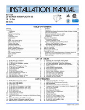
York ZF SERIES Installation Manual (65 pages)
Brand:
York
| Category:
Air Conditioner
| Size: 2.64 MB
Table of Contents
Table of Contents
1
General
2
Installation
5
Preceding Installation
5
Unit Shipping Bracket
5
Condenser Covering
5
Compressor Section
5
Limitations
6
Component Location (ZF120 Shown)
6
Location
7
Rigging and Handling
7
ZF120-150 Unit Limitations
7
Weights and Dimensions Imperial
8
Weights and Dimensions Metric
8
Unit 4 Point Load Weight
8
Unit 6 Point Load Weight
8
Center of Gravity
8
ZF120-150 Unit Accessory Weights Imperial
9
ZF120-150 Unit Accessory Weights Metric
9
ZF120 Unit Dimensions
9
ZF120-150 Unit Physical Dimensions Imperial
10
ZF120-150 Unit Physical Dimensions Metric
10
ZF150 Unit Dimensions
10
ZF120-150 Unit Clearances Imperial
11
ZF120-150 Unit Clearances Metric
11
ZF120-150 Unit Bottom Duct Openings
12
ZF120-150 Unit Electrical Entry
13
ZF120 Unit Side Duct Openings
13
ZF Side Duct Dimensions Imperial
14
ZF Side Duct Dimensions Metric
14
ZF150 Unit Side Duct Openings
14
ZF120 - 150 Unit Left Duct Opening
14
Ductwork
15
ZF120-150 Roof Curb
15
ZF120-150 Transition Roof Curb
15
Side Panels
16
Condensate Drain
16
Side Panels with Hole Plugs
16
Return Downflow Plenum with Panel
16
Discharge Panel in Place
16
Save Side Panels for Economizer Hood Tops
16
Compressors
17
Filters
17
Power and Control Wiring
17
Condensate Drain
17
Field Wiring Disconnect - Cooling Unit With/Without Electric Heat 18 23 Field Wiring Disconnect - Cooling Unit with Gas Heat
19
Control Wire Sizes
20
Typical Electronic Thermostat Field Wiring
20
Electrical Data
21
ZF120-150 Physical Data
22
Optional Electric Heat
24
Electric Heat Minimum Supply Air Imperial
24
Electric Heat Minimum Supply Air Metric
24
Optional Gas Heat
25
Gas Heat Minimum Supply Air Imperial
25
Gas Heat Minimum Supply Air Metric
25
Side Entry Gas Piping
25
Bottom Entry Gas Piping
25
Gas Connection
26
Gas Pipe Sizing - Capacity of Pipe
26
Options/Accessories
27
Optional Hot Gas Bypass (HGBP)
28
Economizer Sequences
28
Dry Bulb Changeover
28
Single Enthalpy Changeover
28
Dual Enthalpy Changeover
28
Auto
28
Free Cooling Operation
29
Power Exhaust
29
Smart Equipment™ Economizer Board Details
30
SE-ECO1001-0 Economizer Controller
30
Supply Air Limitations
33
Belt Adjustment
34
Airflow Performance - Side Duct Application
35
Airflow Performance - Bottom Duct Application
38
Air Balance
41
Checking Air Quantity
41
Indoor Blower Specifications
41
Power Exhaust Specifications
41
Dry Coil Delta P 50" Cabinet
42
Motor Sheave Datum
43
Sequence of Operation
45
Cooling Sequence of Operation
45
No Outdoor Air Options
45
Additional Static Resistance ZF120/150 Cabinet (Imperial) . 44 28 Additional Static Resistance ZF120/150 Cabinet (Metric)
45
Cooling Operation Errors
46
Electric Heating Sequence of Operations
48
Electric Heat Operation Errors
48
Gas Heating Sequence of Operations
48
Ignition Control Board
48
Electric Heat Limit Setting
48
Electric Heat Anticipator Setpoints
48
Gas Heating Operation Errors
49
Gas Heat Limit Settings
50
Gas Heat Anticipator Setpoints
50
Start-Up (Cooling)
51
Start-Up (Gas Heat)
51
Checking Gas Heat Input
51
Gas Rate Cubic Feet Per Hour
52
Gas Heat Stages
53
Typical Flame
53
Typical Gas Valve
53
Charging the Unit
54
Ignition Control Flash Codes
54
Unit Control Board
54
Smart Equipment™ UCB Details
55
Start-Up Sheet
60
York ZF SERIES Instruction Manual (71 pages)
Brand:
York
| Category:
Air Conditioner
| Size: 3.27 MB
Table of Contents
Table of Contents
1
General
2
Installation
5
Limitations
5
ZF180-300 Unit Limitations
6
ZF180-300 Component Location
6
Location
7
Rigging and Handling
7
Weights and Dimensions
8
Unit 4 Point Load Weight
8
Unit 6 Point Load Weight
8
Center of Gravity
8
ZF180-300 Unit Accessory Weights
9
Utilities Entry
9
Supply Fan VFD Weights, in Lbs
9
ZF180-300 Unit Dimensions Front View
9
ZF180-300 Unit Dimensions Rear View
10
ZF180-300 Unit Clearances
11
ZF180-300 Unit Dimensions Rain Hood
11
Ductwork
12
ZF180 Roof Curb
12
ZF210-300 Roof Curb
12
Condensate Drain
13
Compressors
13
Fixed Outdoor Air Damper
13
Filters
14
Power and Control Wiring
14
Control Wire Sizes
15
Field Wiring Disconnect - Cooling Unit With/Without Electric Heat
15
Typical Field Wiring 24 Volt Thermostat
16
Electrical Data
17
ZF180-300 Physical Data
26
Optional Electric Heat
27
Electric Heat Minimum Supply Air
27
Optional Gas Heat
28
Gas Application Data
28
Gas Pipe Sizing - Capacity of Pipe
28
Gas Heat Minimum Supply Air
28
External Supply Connection External Shut-Off
28
Bottom Supply Connection External Shut-Off
28
Options/Accessories
30
Economizer Sequences
30
Dry Bulb Changeover
30
Single Enthalpy Changeover
30
Vent and Combustion Air Hood
30
Dual Enthalpy Changeover
31
Auto
31
Free Cooling Operation
31
Power Exhaust
31
Setpoints
31
Inputs
31
Outputs
31
Operation
31
Simplicity SE Economizer Board Details
32
SE-ECO1001-0 Economizer Controller
32
Optional BAS-Ready Economizer Power Exhaust Damper Set Point Adjustment
35
Optional Variable Air Volume (VAV)
35
Optional Hot Gas Bypass (HGBP)
37
Belt Adjustment
38
Altitude/Temperature Correction Factors
39
Air Flow Performance - Side Duct Application
41
Air Flow Performance - Bottom Duct Application
44
Air Balance
47
RPM Selection
47
Indoor Blower Specifications
47
Power Exhaust Specifications
47
Pressure Drop Across a Dry Indoor Coil Vs. Supply Air CFM for All Unit Tonnages
48
Sequence of Operation
49
Compressor Operation
49
Cooling Operation Errors
49
Electric Heating Sequence of Operations
50
Electric Heat Operation Errors
51
Limit Control Setting
51
Gas Heating Sequence of Operations
52
Electric Heat Anticipator Setpoint
52
Gas Valve Piping
52
Gas Heating Operation Errors
53
Gas Heat Limit Control Setting
53
Gas Valve and Controls
53
Start-Up (Cooling)
54
Start-Up (Gas Heat)
54
Gas Heat Anticipator Setpoints
54
Checking Gas Heat Input
55
Gas Rate Cubic Feet Per Hour
55
Proper Pilot Flame Adjustment
56
Typical Flame
56
Typical Gas Valve
56
Charging the Unit
57
ZF180 (15 Ton) Charging Chart
57
ZF210 (17.5 Ton) Charging Chart
57
ZF240 (20 Ton) Charging Chart
57
ZF300 (25 Ton) Charging Chart
57
Simplicity™ SE (Smart Equipment) Firmware Version
58
Basic Unit Control Board Navigation Examples
58
Simplicity SE UCB Details
60
Unit Control Board
60
Start-Up Sheet
66
1088917-Yim-B-1014
71
York ZF SERIES Installation Manual (54 pages)
R-410A 15 Ton/53 KW 50 Hertz
Brand:
York
| Category:
Air Conditioner
| Size: 1.88 MB
Table of Contents
Table of Contents
1
General
2
Installation
5
Limitations
5
ZF180 Unit Limitations
6
ZF180 Component Location
6
Location
7
Rigging and Handling
7
ZF180 Unit Weights Imperial
8
ZF180 Unit Weights Metric
8
ZF180 Unit Accessory Weights Metric
8
ZF180 Unit Accessory Weights Imperial
8
Unit 4 Point Load Weight
8
Unit 6 Point Load Weight
8
Center of Gravity
8
Unit Dimensions - ZF Cooling Only
9
Unit Dimensions - ZF Gas Heat
9
Utilities Entry Data
10
ZF180 Unit Dimensions Rear View
10
ZF180 Unit Clearances
11
ZF180 Unit Dimensions Rain Hood
11
Ductwork
12
Roof Curb Dimensions (All Models)
12
Roof Curb Benefits
12
Unit Curb and Applications
12
Condensate Drain
13
Compressors
13
Fixed Outdoor Air Damper
13
Filters
14
Power and Control Wiring
14
Control Wire Sizes
15
Heat
15
Typical Field Wiring 24 Volt Thermostat
16
Electrical Data
17
ZF180 Physical Data
18
Optional Gas Heat
20
Gas Application Data
20
Gas Pipe Sizing - Capacity of Pipe
20
Gas Heat Minimum Supply Air Imperial
20
Gas Heat Minimum Supply Air Metric
20
External Supply Connection External Shut-Off
20
Bottom Supply Connection External Shut-Off
20
Options/Accessories
22
Economizer Sequences
22
Dry Bulb Changeover
22
Single Enthalpy Changeover
22
Dual Enthalpy Changeover
22
Auto
22
Free Cooling Operation
22
Vent and Combustion Air Hood
22
Power Exhaust
23
Setpoints
23
Inputs
23
Outputs
23
Operation
23
Smart Equipment™ Economizer Board Details
24
SE-ECO1001-0 Economizer Controller
24
Belt Adjustment
27
Altitude/Temperature Correction Factors Imperial
28
Altitude/Temperature Correction Factors Metric
28
Altitude/Temperature Correction Factors Imperial
29
Altitude/Temperature Correction Factors Metric
29
ZF180 Side Duct Application
31
Air Flow Performance - Side Duct Application
31
Air Flow Performance - Bottom Duct Application
32
Air Balance
33
RPM Selection
33
Indoor Blower Specifications
33
Power Exhaust Specifications
33
Pressure Drop Across a Dry Indoor Coil Vs. Supply Air CFM
33
Additional Static Resistance Imperial
34
Additional Static Resistance Metric
34
Sequence of Operation
35
Cooling Sequence of Operation
35
No Outdoor Air Options
35
Cooling Operation Errors
36
Electric Heating Sequence of Operations
37
Electric Heat Operation Errors
37
Limit Control Setting
37
Gas Heating Sequence of Operations
38
Gas Heating Operation Errors
38
Electric Heat Anticipator Setpoint
38
Gas Valve Piping
38
Gas Heat Limit and Auxiliary Location down Discharge
39
Application
39
Gas Heat Limit and Auxiliary Location Side Discharge
39
Start-Up (Cooling)
40
Gas Heat Limit Control Setting
40
Gas Heat Anticipator Setpoints
40
Gas Valve and Controls
40
Start-Up (Gas Heat)
41
Checking Gas Heat Input
41
Gas Rate Cubic Feet Per Hour
41
Proper Pilot Flame Adjustment
42
Typical Flame
42
Typical Gas Valve
42
Smart Equipment™ UCB Details
43
Unit Control Board
43
Start-Up & Service Data Instruction
49
York ZF SERIES Technical Manual (104 pages)
R-410A ZJ/ZR/ZF SERIES 15 - 25 TON 60 Hertz
Brand:
York
| Category:
Air Conditioner
| Size: 2.59 MB
Table of Contents
Description
1
Table of Contents
2
Component Location
3
Nomenclature
4
Features and Benefits
5
Guide Specifications
9
Physical Data
15
Capacity Performance
21
Airflow Performance
49
Sound Performance
69
Electrical Data
70
Weights and Dimensions
96
Unit Dimensions
98
Utilities Entry
98
York ZF SERIES Wiring Diagrams (95 pages)
R-410A, 3 - 6 Ton, 60 Hertz
Brand:
York
| Category:
Air Conditioner
| Size: 15.21 MB
Advertisement
Related Products
York ZF 180 Series
York ZF210
York ZF 240 Series
York ZF300
York ZF036
York ZF048
York ZF060
York ZF076
York Predator ZF120
York Predator ZF102
York Categories
Air Conditioner
Heat Pump
Chiller
Furnace
Air Handlers
More York Manuals
Login
Sign In
OR
Sign in with Facebook
Sign in with Google
Upload manual
Upload from disk
Upload from URL