Sign In
Upload
Manuals
Brands
York Manuals
Air Conditioner
YIDM015B21S
York YIDM015B21S Manuals
Manuals and User Guides for York YIDM015B21S. We have
1
York YIDM015B21S manual available for free PDF download: Service Manual
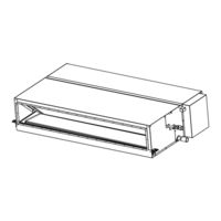
York YIDM015B21S Service Manual (186 pages)
INVERTER-DRIVEN MULTI-SPLIT SYSTEM HEAT PUMP AIR CONDITIONERS
Brand:
York
| Category:
Air Conditioner
| Size: 14.09 MB
Table of Contents
Important Notice
3
General Precautions
5
Important Safety Instructions
5
Installation Precautions
7
Refrigerant Precautions
8
Table of Contents
11
1 Installation
15
Outdoor Unit
16
Change-Over Box
16
Indoor Unit
16
Control Device
17
Wired Controller: Ciw01
17
Simplified Wired Controller: Cis01
17
Wireless Controller: Cir01
17
Mini Central Controller: Ccm01
17
Large Central Controller: Ccl01
17
Computerized Central Controller Management Software: Cccs01
17
Computerized Central Controller Software / Operation Ratio For Cccs01
17
Computerized Central Controller Adapter: Ccca01
17
Infrared (Ir) Receiver Kit: CWDIRK01
17
Optional Parts
18
Air Filter: Kw-PP3Q, KW-PP4Q
18
Air Filter: Kw-PP7Q, KW-PP8Q, KW-PP9Q, KW-PP10Q
18
Air Filter: Kw-PP5Q, KW-PP6Q
18
Relay And 3 Pin Connector Kit: Psc-5RA
18
Remote Sensor: Thm-R2A
18
Connector Cable: Pcc-1A
18
2 Operation
19
Indoor Unit
20
Control Device
21
Wired Controller: Ciw01
21
Simplified Wired Controller: Cis01
21
Mini Central Controller: Ccm01
21
Large Central Controller: Ccl01
21
Computerized Central Controller Management Software: Cccs01
21
Computerized Central Controller Software / Operation Ratio For Cccs01
21
Infrared (Ir) Receiver Kit: Cwdirk01
21
3 Troubleshooting
23
Initial Troubleshooting
24
Checking Electrical Wiring And Power Supply
24
Location Of Printed Circuit Boards (Pcbs)
28
Checking Rotary Switch And Dip Switch Settings
29
Checking Wired Controller
32
Checking Using 7-Segment Display
38
Checking Alarm Code History
38
Emergency Operation
38
Troubleshooting Procedures
39
Alarm Code Table
40
Troubleshooting Using Alarm Codes
41
Alarm Code
52
Abnormalities Of Devices
57
Procedures For Checking
69
Self-Checking Of Pcbs Using Wired Controller
69
Self-Checking Of Wired Controller
69
Test Run
70
Test Run Using Wired Controller
71
Test Run From Outdoor Unit Side
73
Checking The Test Run
73
Check List For Refrigerant System
74
Reset For Accumulated Operation Time Of Compressor 1-2 (Cuj1- Cuj2)
74
4 Maintenance
75
Maintenance Of Outdoor Unit
76
Maintenance Of Indoor Unit
77
Ducted High Static Type ((H,Y)Idh018 - 048B21S)
77
Removing Long-Life Filter
77
Removing Pcb
77
Removing Fan And Fan Motor
78
Removing Thermistors For Liquid Pipe And Gas Pipe
85
Removing Electronic Expansion Valve Coil
86
Removing Float Switch
86
Removing Condensate Pump
87
Removing Condensate Pan
88
Ducted Medium Static Type ((H,Y,C)Idm006 - 048B21S)
91
Removing Long-Life Filter
91
Removing Pcb
91
Removing Fan And Fan Motor
92
Removing Thermistors For Liquid Pipe And Gas Pipe
97
Removing Electronic Expansion Valve Coil
98
Removing Float Switch
98
Removing Condensate Pump
99
Removing Condensate Pan
100
Ducted Slim Type ((H,Y,C)Ids006 - 018B21S)
103
Removing Long-Life Filter
103
Removing Pcb
103
Removing Fan And Fan Motor From Bottom Side (For All Models)
104
Removing Thermistors For Liquid Pipe And Gas Pipe
108
Removing Electronic Expansion Valve Coil
109
Removing Float Switch
109
Removing Condensate Pump
110
Removing Condensate Pan
111
Cleaning Indoor Unit Heat Exchanger
113
Required Tools For Cleaning
113
Cleaning Procedure
114
Main Parts
117
For Outdoor Unit
117
For Change-Over Box
117
For Indoor Units
118
Printed Circuit Board
118
Fan Motor
121
Thermistor
126
Electronic Expansion Valve
128
5 External Input/Output And Function Setting
131
Dip Switch Settings Of Outdoor Unit
132
High Static Pressure Setting (Dsw5-No.5: On)
132
External Input/Output And Function Setting Mode For Outdoor Unit
132
External Input/Output And Function Setting Mode For Indoor Unit
133
External Input And Output Settings
135
Remote Control On/Off Function
136
Power Supply On/Off 1 (Automatic Operation When Power Supply Is On)
141
Power Supply On/Off 2 (Restarting Function After Power Failure)
141
Control by Field-Supplied Room Thermostat [ Input Setting: Code (01) (for Cooling), Code (02) (for Heating) ]
142
Remote Cooling/Heating Change [ Input Setting: Code (07) ]
143
Picking Up Operation Signal
144
Function Setting
147
Function Selection Item
147
Description Of Function Selection Item
154
Functions From Wired Controller
168
Power Saving Function
168
Schedule Function
170
Indication Function
170
Comfort Function
171
6 Field Work Instructions
173
Caution For Refrigerant Leakage
174
Modifications Of Charging Refrigerants Other Than Those Specified By Johnson Controls
175
Maintenance Work
176
Service And Maintenance Record By 7-Segment Display
177
Service And Maintenance Record By Wired Controller
178
Service And Maintenance Record
180
Saturation Curve For Refrigerant
181
Mollier Chart For R410A
182
7 Service Parts List
183
Advertisement
Advertisement
Related Products
York YIDM012B21S
York YIDM018B21S
York YIDM006B21S
York YIDM008B21S
York YIDM024B21S
York YIDM030B21S
York YIDM048B21S
York YIDM036B21S
York YIDM036B21E
York YIDM048B21E
York Categories
Air Conditioner
Heat Pump
Chiller
Furnace
Air Handlers
More York Manuals
Login
Sign In
OR
Sign in with Facebook
Sign in with Google
Upload manual
Upload from disk
Upload from URL