Sign In
Upload
Manuals
Brands
wolke Manuals
Printer
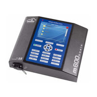
m600 basic
wolke m600 basic Manuals
Manuals and User Guides for wolke m600 basic. We have
3
wolke m600 basic manuals available for free PDF download: Operating Manual, Operator's Manual
wolke m600 basic Operating Manual (218 pages)
Brand:
wolke
| Category:
Printer
| Size: 10 MB
Table of Contents
Table of Contents
5
1 Identification
19
Type of Printer
19
Manufacturer 1 Contents
19
Intended Use
19
2 General Instructions and Information
20
Warranty and Liability
20
Archiving the Operating Manual
20
3 Safety Instructions
21
General Instructions and Information
21
Duties of the Company Operating the System
21
Duties of the Staff
21
Input
21
Hazards Associated with Handling the M600 Basic
22
4 Installation
23
Integral Parts and Accessories of the M600 Basic
23
Fig. 4_1: Controller
23
Fig. 4_2: Print Heads
23
Fig. 4_3: Connector Cable from Print Head to the Controller; One Cable/Print Head
24
Fig. 4_4: Scraper Plates
24
Fig. 4_5: Sensor
24
Fig. 4_8: HP Cartridge
25
Fig. 4_9: Protective Caps for Cartridges
25
Fig. 4_10: Mounting Kit for 1-Head Mounting
25
Fig. 4_11: Adjusting Unit for Multi-Head Mounting
25
Fig. 4_12: Parallelogram with Locating Wheel
26
Fig. 4_13: Deflector and Locating Wheel
26
Fig. 4_14: Pulse Generator
26
Fig. 4_15: Measuring Wheels for Pulse Generator
27
Fig. 4_16: Resilient Pulse Generator Mount
27
Fig. 4_17: Pulse Generator Cable
27
Fig. 4_18: Warning Beacon
27
Fig. 4_19: I/O-Box
27
Controller
28
Installation
28
Fig. 4_20: Controller
28
Terminals
29
Fig. 4_21: Front Side
29
Fig. 4_22: Rear of Controller - Connectivity
29
IP65 Caps on the Controller's Rear Side
30
Fig. 4_23: Rear of Controller with Caps
30
Print Head and HP Cartridge
31
Fig. 4_24: Standard Print Head (in this Case with a Conventional Photoelectric Cell)
31
Fig. 4_25: Red Print Head
32
Fig. 4_26: Green Print Head
32
Fig. 4_27: Golden Print Head
32
Positioning of Print Head
33
Print Head Arrangement
33
Fig. 4_28: Print Head Positioning Options
33
Fig. 4_29: Examples - Equipment of the M600 Basic with Two Print Heads
33
Installing the Print Heads
34
Selection of a Suitable Installation Position
34
Fig. 4_30: Printing Head According to the Number of Print Heads
34
Photoelectric Cell
35
Fig. 4_31: Selection of a Installation Position
35
Fig. 4_32: Photoelectric Cell (Keyence)
35
Position of Photoelectric Cell
36
Installing the Photoelectric Cell
36
Fig. 4_33: Position of Photoelectric Cell
36
Fig. 4_34: Cutter for Optical Fibre
36
Fig. 4_35: Cutting the Optical Fiber to Size
37
Settings of Photoelectric Cell
39
Fig. 4_36: Adjusting Photoelectric
39
Detection of a Measuring Object
40
Pulse Generator (Optional)
42
Installation of the External Pulse Generator
42
Fig. 4_37: Pulse Generator and Rubber Measuring Wheel
42
Fig. 4_38: Mounting the External Pulse Generator
42
Fig. 4_39: Various Measuring Wheel Versions
43
Fig. 4_40: Resilient Pulse Generator Mount
43
Installation by Means of the Mounting System (Optional)
44
Fig. 4_41: Mounting System for 1-Head Mounting of a Blue Print Head
44
Fig. 4_42: Adjusting Unit for Multi-Head Mounting
44
Fig. 4_43: Mounting Adapter for Green, Red and Gold Colored Print Heads
44
Fig. 4_44: Mounting Adapter for Gold Colored Print Heads
44
Fig. 4_45: Example with Reference to 1-Head Mounting (Using a 1-Head Mounting System)
45
Fig. 4_46: Stainless Steel Mounting System for the Red and Green Print Head
45
Fig. 4_47: Stainless Steel Mounting Adapter for the Blue Print Head
45
Fig. 4_48: Stainless Steel Mounting Adapter for the Golden Print Head
45
Installation by Means of the Parallelogram (Optional)
46
Fig. 4_49: Parallelogram
46
Fig. 4_50: Possible Positions of the Parallelogram
46
Connecting the Printer Components
48
Fig. 4_51: Connect the Connector Cable from the Print Head to the Controller
48
5 Operation
49
Keyboard
49
Fig. 5_52: Keyboard
49
Display
50
Fig. 5_53: Main Menu
50
Fig. 5_54: Main Menu - Continued
50
Tab. 5_1: Key Assignment - Overview
50
Fig. 5_55: Example - Menus with Several Options
51
Fig. 5_56: Example - Fields for User-Defined Editing
51
Navigation
51
Fig. 5_57: Lists, Example 1
52
Fig. 5_58: Lists, Example 2
52
Main Menu
53
Fig. 5_59: Main Menu - Overview
53
6 Settings
54
Fig. 6_60: Main Menu > Settings
54
Fig. 6_61: Main Menu > Settings > System
55
Date
56
Fig. 6_62: Settings > System > Date
56
Time
57
Language
57
Fig. 6_63: Settings > System > Time
57
Network
58
Fig. 6_64: Settings > System > Language
58
Fig. 6_65: Settings > System > Network
58
Fig. 6_66: Network > Assigning a Device Name
58
Fig. 6_67: Network > Autom. Network Address
59
Fig. 6_68: Network > Autom. Network Address > off
59
Password
60
Fig. 6_69: Settings > System > Password
60
Fig. 6_70: Password > User > User1 > Rename
61
Fig. 6_71: Password > User > User1 > Password
61
Fig. 6_72: User > User 1 > Access Rights
62
Fig. 6_73: User 1 > Access Rights > System Settings
64
Fig. 6_74: User1 > Delete Passwords
64
Screen Saver
65
Fig. 6_75: Password Deleted
65
Fig. 6_76: System > Screen Saver
65
Fig. 6_77: Autom. Screen Saver >Activation / Deactivation
65
Factory Settings
66
Fig. 6_78: Autom. Screen Saver > Delay [Min]
66
Fig. 6_79: Settings > System > Factory Settings
66
Installation
67
Fig. 6_80: Settings > Installation
67
Pulse Generator/Pulses/Speed
68
Fig. 6_81: Installation > Pulse Generator > Internal/External
68
Fig. 6_82: Installation > Speed [M/Min]
68
Fig. 6_83: Installation > Pulses/M
69
Input 1
71
Fig. 6_84: Installation > I/O
71
Fig. 6_85: External Input 1
71
Input 2
72
Fig. 6_86: External Input 2
72
Fig. 6_87: External Input 3
72
Fig. 6_88: External Input 4
73
External Output 4
74
Print Heads and Print Head Configuration
74
Fig. 6_89: External Output 4
74
Fig. 6_90: Installation > Print Head 1
74
Fig. 6_91: Print Head 1 > Product Sensor
75
Fig. 6_92: Print Head 1 > Mirrored
75
Fig. 6_93: Print Head 1 > Reflected
75
Fig. 6_94: Print Head 1 > Printing Direction
76
Fig. 6_95: Print Head 1 > Sensor Distance [MM]
76
Various System Settings
77
Fig. 6_96: Factory Setting - Menu Settings Print Head 1 and 2
77
Fig. 6_97: Alternative a - Menu Settings Print Head 1 and 2
78
Fig. 6_98: Alternative B - Menu Settings Print Head 1 and 2
78
Spitting
79
Fig. 6_99: Alternative C - Menu Settings Print Head 1 and 2
79
Fig. 6_100: System > Spitting
80
Fig. 6_101: Spitting > Autom. Spitting > Activation / Deactivation
80
Fig. 6_102: Spitting > Waiting Time [S]
80
Image Refresh
81
Fig. 6_103: Spitting > Spitting Time [S]
81
Fig. 6_104: Installation > Image Refresh
81
Cartridge
82
Fig. 6_105: Installation > Image Refresh > Activating Editing for Image Refresh
82
Fig. 6_106: Installation > Image Refresh > Waiting Time [S]
82
Fig. 6_107: Settings > Cartridge > Print Head 1/2
82
Fig. 6_108: Settings > Cartridge > Print Head 1
83
Print Head 1/2
83
Cartridge Size - Type
84
Fig. 6_109: Cartridge > Print Head 1 > Type
84
Ink Type
85
Fig. 6_110: Cartrdige > Print Head 1 > Ink Type
85
Tab. 6_5: Ink Type
86
Temperature-Controlled
87
Cartridge Size Identical
87
Fig. 6_111: Cartridge > Print Head 1 > Temperature-Controlled
87
Fig. 6_112: Cartridge > Print Head 1 > Cartridge Size Identical
87
Alarm Function
88
Cartridge Empty" Threshold
88
Fig. 6_113: Cartridge > Print Head 1 > Alarm
88
Fig. 6_114: Cartridge > Print Head 1 > Treshold
88
Error - Cartridge Removed
89
Fig. 6_115: Settings > Cartridge > Print Head 2
89
Fig. 6_116: Message „Print Head Error
89
Print Head 2
89
7 Label
90
Fig. 7_117: Main Menu > Label
90
Fig. 7_118: 2-Head Label
91
Field Types
92
Fig. 7_119: Edit > New Object > Text1
93
Fig. 7_120: Text Input
93
Fig. 7_121: Text Object - Entry of Font Size
94
Fig. 7_122: Text Object - Definition X Position
94
Fig. 7_123: Text Object - Definition y Position
95
Fig. 7_124: Delete Text Object
95
Bitmap
96
Fig. 7_125: New Object Bitmap
96
Fig. 7_126: Selection of the Required Bitmap
96
Barcodes
97
Ean13/Ean8
98
Fig. 7_127: New Object Barcode
98
Fig. 7_128: Selection of Barcode
98
Fig. 7_129: Determination of the Barcode Parameters
98
Fig. 7_130: Barcode Parameters - Continued
99
Fig. 7_131: Barcode - Value
99
Fig. 7_132: Barcode - Embedded Fields
100
Fig. 7_133: Determining Height of Barcode
100
Fig. 7_134: Barcode - Scaling
100
Fig. 7_135: Barcode - Bar Width Reduction
101
Fig. 7_136: Patterns with Identical Scaling and Different Reduction
101
Fig. 7_137: Example - Barcode with and Without Numerical Plain Text Line
102
Fig. 7_138: Activation/Deactivation of Plain Text Line
102
Upc-A
103
Fig. 7_139: Barcode - Type UPC-A
103
Code128/Ean128
104
Fig. 7_140: Barcode - Type Ean128/Code128
104
Fig. 7_141: Determination of Text Position
105
Fig. 7_142: Barcode - Defining the Distance
105
2/5I
106
Fig. 7_143: Barcode - Type 2/5I
106
Fig. 7_144: Activation/Deactivation of Check Digit Calculation
107
Fig. 7_145: Barcode - Ratio
107
Code39
108
Fig. 7_146: Example Print Code39
108
Fig. 7_147: Barcode - Type Code39
108
Datamatrix
109
Fig. 7_148: Barcode Type Datamatrix
109
Tab. 7_6: GS1 Application Identifier - Excerpt
110
Tab. 7_7: Possible Matrix Sizes of the Datamatrix
110
Fig. 7_149: Drawing for the Datamatrix
111
Fig. 7_150: Example Datamatrix
112
Date
113
Fig. 7_151: New Objekt - Date
113
Tab. 7_8: Format Parameters in the Date Field
114
Fig. 7_152: Date Templates
114
Fig. 7_153: Date - Lead
115
Fig. 7_154: Date - Lead Mode
115
Fig. 7_155: Date - Offset (Minute)
115
Fig. 7_156: Date - Offset (Hour)
116
Fig. 7_157: Date - Update
116
Fig. 7_158: Date - Interval, Update Weekly
116
Tab. 7_9: Examples for Update Mode and Intervals
117
Fig. 7_159: Date - Interval, Update Monthly
117
Fig. 7_160: Date - Font Size
118
Fig. 7_161: Date - X Position
118
Fig. 7_162: Date - y Position
118
Fig. 7_163: Delete Date Field
118
Time
119
Fig. 7_164: New Object Time
119
Fig. 7_165: Time - Templates
119
Tab. 7_10: Format Parameters in the Time Field
120
Fig. 7_166: Time - Individual
120
Fig. 7_167: Time - Font Size
120
Fig. 7_168: Time - X Position
121
Fig. 7_169: Time - y Position
121
Fig. 7_170: Delete Time Field
121
Counter
122
Fig. 7_171: New Object Counter
122
Fig. 7_172: Counter Status
122
Fig. 7_173: Counter - Start Value
123
Fig. 7_174: Counter - End Value
123
Fig. 7_175: Counter - Number of Digits
123
Fig. 7_176: Counter - Step Size
124
Fig. 7_177: Counter - Leading Zeros
124
Fig. 7_178: Counter - Batch Number
125
Fig. 7_179: Counter - Start Values of Series
125
Fig. 7_180: Counter - Update
125
Fig. 7_181: Actualization Behaviour - Update Per Print
126
Fig. 7_182: Actualization Behaviour - Update Per Sensor Signal
126
Fig. 7_183: Counter - Final Value Reached
127
Fig. 7_184: Counter - Font Size
127
Fig. 7_185: Counter - X Position
127
Shift
128
Fig. 7_186: Counter - y Position
128
Fig. 7_187: Delete Counter
128
Fig. 7_188: New Object Shift
128
Fig. 7_189: Number of Shifts
129
Fig. 7_190: Beginning of Shift
129
Fig. 7_191: Shift Name
130
Fig. 7_192: Shift - Font Size
130
Fig. 7_193: Shift - X Position
131
Fig. 7_194: Shift - y Position
131
Fig. 7_195: Delete Shift
131
Creating a Label
132
Fig. 7_196: Label Templates - Examples
132
Fig. 7_197: Example - Template 1Head
132
Fig. 7_198: Preview Demo1
132
Fig. 7_199: Edit Demo1
133
Fig. 7_200: Demo1 -New Object
133
Label Settings
134
Fig. 7_201: Label Settings
134
Font
135
Size & Resolution
135
Fig. 7_202: Label Settings - Font
135
Fig. 7_203: Label Settings - Size and Resolution
135
Fig. 7_204: Size & Resolution - Number of Print Heads
136
Fig. 7_205: Size & Resolution - Grouping
136
Fig. 7_206: Size & Resolution - Nozzle Rows
137
Fig. 7_207: Printing Example with 1 Nozzle Row = 300 Dpi
137
Fig. 7_208: Printing Example with 2 Nozzle Rows = 600 Dpi
137
Tab. 7_11: Resolution and Max. Speed of the Product
138
Fig. 7_209: Size & Resolution - Resolution
138
Tab. 7_12: Setting the „Distance After" Regarding the Speed and Data Volume
139
Label Size
140
Fig. 7_210: Label Settings - Label Size Head 1
140
Fig. 7_211: Head 1 - Distance before
141
Fig. 7_212: Head 1 - Print Length
141
Fig. 7_213: Head 1 - Distance after
142
Other Parameters
143
Fig. 7_214: Label Size - Label Parameters
143
Fig. 7_215: Label Parameter - Autostart
143
Fig. 7_216: Label Parameter - Limited Output
144
Fig. 7_217: Label Parameter - Number Limited
144
Fig. 7_218: Photoelectric Cell Pulse, E.g. Caused by a Carton Edge
145
Fig. 7_219: Label Parameter - Cyclic
145
Fig. 7_220: Photoelectric Cell Pulse, E.g. Caused by a Paper Edge
146
Fig. 7_221: Photoelectric Cell Pulse, E.g. Caused by Printmarks
146
Example - Creating a Straightforward Label
147
Fig. 7_222: Label Parameter - Number/Sensor
147
Loading and Printing Label File
151
Fig. 7_223: Select Label File
151
Fig. 7_224: Menu Label > Load
151
8 Diagnosis
152
Start Diagnosis
152
Fig. 8_225: Main Menu - Diagnosis
152
Fig. 8_226: Diagnosis > Start Diagnosis
152
Fig. 8_227: Diagnosis Print Head 1
153
Print Head 1/2
153
Inputs and Outputs
155
Inputs
155
Outputs
155
Fig. 8_228: Start Diagnosis > Inputs
155
Fig. 8_229: Start Diagnosis > Outputs
155
Product Sensor (Ps)/Encoder
156
Fig. 8_230: Start Diagnosis > Product Sensor/Encoder
156
Fig. 8_231: Replace Cartridge Print Head 1
157
Replace Cartridge
157
Fig. 8_232: Cartridge Reset
158
Fig. 8_233: Various Indications of the Warning Beacon
158
Status Displays of the Warning Beacon
158
9 Info
159
Fig. 9_234: Main Menu > Info
159
10 Show Current Print Label
160
Fig. 10_235: Main Menu > Show Current Print Label
160
11 Logon
161
Fig. 11_236: Main Menu > Logon
161
12 Replacement of Cartridge
162
Inserting the HP Cartridge into Various Print Heads
162
13 Data Exchange
164
Data Exchange Via Stick
164
Fig. 13_237: Main Menu File Management
164
Fig. 13_238: Standard Folders on the USB Stick
165
Fig. 13_239: Contents of USB Stick with Data Backup
165
Loading Files
166
Fig. 13_240: Several Data Backups in the Folder "M600Backup
166
Fig. 13_241: Loading Files
166
Backup of Files
170
Deleting Files
170
Data Exchange Via Host Computer
171
Fig. 13_242: Example - Label with S/N on the Front Side of the Controller
171
Restrictions of the Functions of the Label Designer
174
Software-Update
175
14 Technical Data
179
Technical Drawings
179
Terminals
185
Power Supply
185
Pulse Generator Socket
185
Tab. 14_13: Supply Voltage
185
Tab. 14_14: Values for Pulses/Meters Depending on Measuring Wheel Diameter
185
Tab. 14_15: Connector Pin Assignment - Pulse Generator Socket
186
Tab. 14_16: Specifications for the Pulse Generator Connection
186
Fig. 14_243: Output Signal Profile of Pulse Generator
187
Fig. 14_244: External Circuitry for Shaft Encoder of Other Manufacturers with
188
Pulse Generator Extension Cables
189
Tab. 14_17: Connector Pin Assignment - Pulse Generator Extension Cables
189
External Inputs and Outputs
190
14.2.4.1 24 V DC Socket Version
190
Tab. 14_18: Connector Pin Assignment of the 24 V DC I/O Socket
190
Tab. 14_19: Limits for the 24 V Input Interface
191
Tab. 14_20: Limits for the 24 V DC Output Interface
191
Tab. 14_21: Connection Example Signal Light with 5 Meter I/O Cable
191
Fig. 14_245: Wiring Example for the 24 V DC Interface
192
Print Head Socket
193
Photoelectric Cell on the Print Head of the M600 Basic
193
Tab. 14_22: Pin Assignment of the Photoelectric Cell
193
15 Service and Maintenance
194
Information on Care
194
Storage of Ink Cartridges
194
Cleaning the Cartridges
194
Maintenance Instructions
195
16 M600 Basic Data Sheet
196
17 Declaration of Conformity
197
Label
199
18 Faq
207
Printing
207
Spitting
211
Cartridge
211
Operator Control
211
Communication M600 Basic - PC
212
Display
212
Diagnosis
213
Miscellaneous
213
19 Screen Messages
214
Index
217
Advertisement
wolke m600 basic Operator's Manual (166 pages)
Brand:
wolke
| Category:
Printer
| Size: 8 MB
Table of Contents
Compliance Information
3
For Customers in Canada
4
For Customers in the European Union
4
Support and Training
5
Contact Information
5
Customer Training
5
Fluids
5
Table of Contents
6
Chapter 1 - Introduction
10
Wolke M600 Touch Printer
10
Equipment Description
10
About the Manual
11
Related Publications
11
Language Codes
11
Content Presentation
13
Positional References
13
Units of Measurement
13
Safety Information
13
Notes
14
Abbreviations and Acronyms
15
Chapters in the Manual
15
Chapter 2 - Safety
16
Introduction
17
Equipment Safety Guidelines
17
Comply with Electrical Codes
17
Do Not Remove Warning Label
17
Placement of the Printer
18
Printhead Installation Guidelines
18
Ink Safety Guidelines
19
Safety Warnings for Wolke M600 Touch Printer
20
Grounding and Bonding
20
Electrical Power
20
Communications
21
Other Important Guidelines
22
Medical Emergencies
22
Emergencies Involving Printer Ink
22
Chapter 3 - Installation
23
Integral Parts and Accessories
23
Delivery of Parts
23
Main Parts and Accessories
24
Installation of Printhead and Ink Cartridge
32
Special Version Printheads for Printing Different Types of
33
Positioning of Printhead
34
Printhead Arrangement
35
Installing the Printheads
36
Selection of a Suitable Installation Position
36
Photoelectric Cell
37
How to Detect a Measuring Object
43
Shaft Encoder (Optional)
45
Installation of the Mounting System (Optional)
47
Installation of the Parallelogram (Optional)
49
Mounting of Controller
53
Clarity® Controller
53
How to Connect the Printer Components
53
Chapter 4 - Clarity® Operating System
55
Getting Started with the Clarity
55
Using the Home Page
56
Using the Tools Page
57
Working with Setup Page
58
Working with Diagnostics
62
Working with Database
73
Password Protection
74
Chapter 5 - Commissioning
76
How to Insert the Cartridge into the Printhead
76
How to Turn on the Printer
78
How to Set the Screen Orientation
81
Setting up the Printer
82
Language, Region/Country, Date and Time
82
Printhead Settings
83
How to Start the Printer
87
How to Monitor the System
87
How to Stop the Printer
89
How to Select and Print the Test Job
89
How to Setup the Printhead Settings
90
How to Adjust Print Registration
91
How to Purge Printhead
91
How to Adjust Print Resolution
92
How to Change Product Direction
92
How to Change Product Orientation
92
How to Enable/Disable the Printheads
93
How to Configure the Job Settings
93
Size & Resolution
93
How to Set the System Settings
96
Chapter 6 - Printer Operation
97
Viewing the Current Job or Image
97
How to Download a Job File
99
Download Job File from the Personal Computer to the Printer
99
Download a Job from the PC to USB Memory Stick
101
Connecting the USB Database
106
Selecting a New Job
108
User Editable Fields
108
How to Change the Text and Date Fields
109
Touch to Edit
111
Quick Position Edit
114
How to Delete a Job from the Jobs Database
116
How to Set up Counters
118
Time Field/Shift Code
119
Line Select Mode
120
Reverse Print
123
Input Settings
123
How to Replace the Ink Cartridge
124
Production Audit Log
128
Chapter 7 - Maintenance
131
Information on Care
131
Maintaining the Ink Cartridge
132
Storage of Ink Cartridges
132
Cleaning the Ink Cartridges
132
Maintaining the Power Supply
133
Replacing the Mains Fuse
133
Recovering Nozzles/Purge Nozzles
134
To Purge the Printheads When Not in Production
134
Maintaining the Printer
135
Spare Parts List
135
Cables
137
Accessories
137
Chapter 8 - Troubleshooting
138
Fault Messages and Warnings
138
Reading a Fault Message or Warning
138
Clearing a Fault Message or Warning
139
Printing Faults
141
Job Faults
145
Purging Faults
145
Cartridge Faults
145
Line Selection Faults
146
Clarity® Error Messages
146
Other Error Messages
149
Alarms
150
Diagnostics
151
Chapter 9 - Specifications
152
Technical Drawings
152
Printhead, Blue
152
Printhead, Red
153
Printhead, Green
154
Printhead, Gold
154
Sensor
155
Sensor with Installation Mount
156
Adapter Plate for Sensor
157
Spacer Plate for Sensor, for Use with a Locating Wheel
157
Clarity® Controller
158
Parallelogram
159
Technical Specifications
159
System Specifications
160
Networking and External Communications
161
Terminals
162
Power Supply
162
Shaft Encoder Socket
162
Shaft Encoder Extension Cables
165
Glossary
166
wolke m600 basic Operator's Manual (153 pages)
Brand:
wolke
| Category:
Printer
| Size: 6 MB
Table of Contents
Compliance Information
3
For Customers in Canada
4
For Customers in the European Union
4
Support and Training
6
Contact Information
6
Customer Training
6
Fluids
6
Table of Contents
7
Chapter 1 - Introduction
11
Wolke M600 Universal Printer
11
About the Manual
11
Related Publications
11
Language Codes
11
Content Presentation
12
Positional References
13
Units of Measurement
13
Safety Information
13
Notes
14
Abbreviations and Acronyms
14
Chapters in the Manual
15
Chapter 2 - Safety
16
Introduction
17
Equipment Safety Guidelines
17
Comply with Electrical Codes
17
Electrical Power
18
Do Not Remove Warning Label
19
Grounding and Bonding
19
Communications
19
Printhead and Cartridges
19
Fluid Safety Guidelines
20
Other Important Guidelines
21
Medical Emergencies
22
Emergencies Involving Printer Fluids
22
Chapter 3 - Main Parts
23
Equipment Description
23
Clarity Controller
23
Printhead
26
Ink Cartridge
28
Connector Cables
28
Product Sensor
29
Optical Fibre
29
Other Components
30
Shaft Encoder
30
Measuring Wheel for Shaft Encoder
31
Resilient Shaft Encoder Mount
31
Shaft Encoder Cable
31
Warning Beacon
32
Serial Interface Cable and Ethernet Cable
32
USB Connector
33
Mounting System
33
Floor Mount System
35
Parallelogram
35
Chapter 4 - Clarity Operating System
36
Getting Started with the Clarity
36
Using the Home Page
37
Using the Tools Page
39
Working with Setup Page
40
Working with Diagnostics
45
Working with Database
58
Password Protection
59
Chapter 5 - Printer Operation
60
How to Insert the Cartridge into the Printhead
61
Priming the Cartridge
61
Inserting the Cartridge
64
How to Turn on the Printer
64
How to Set the Screen Orientation
67
Setting up the Printer Using System Configuration Wizard
68
Language, Region/Country, Date and Time
69
Printhead Settings
69
How to Setup the Printhead Settings
73
How to Enable/Disable the Printheads
73
How to Adjust Registration Delay
74
How to Change Product Direction
75
How to Change Print Direction
76
How to Adjust Print Resolution
76
How to Change Print Orientation
78
How to Create a Job
78
Inserting Barcodes and 2D Codes into a Job
79
How to Download a Job File
80
Download Job File Using TCP/IP or Serial Connection
80
Download a Job File Using USB Memory Stick
82
Connecting the USB Database
85
How to Load a Job for Printing
88
How to Start the Printer
89
How to Stop the Printer
91
Print Screen Saver
91
Chapter 6 - Additional Printer Operations
93
Viewing the Current Job or Image
94
Selecting a New Job
95
User Editable Fields
96
How to Change the Text and Date Fields
96
Touch to Edit
99
Quick Position Edit
101
How to Delete a Job from the Jobs Database
103
Line Select Mode
105
How to Replace the Cartridge
108
Remove the Old Cartridge
108
Insert the New Cartridge
109
Adjust the Ink Level Manually
110
Production Audit Log
111
How to Update Printer Software
113
Updating by USB Key
114
Updating by Clarity Configuration Manager
114
Chapter 7 - Maintenance
115
Information on Care
115
Maintaining the Cartridge
116
Storage of Cartridge
116
Cleaning the Cartridge
116
Maintaining the Controller and the Printhead
117
Chapter 8 - Troubleshooting
118
Fault Messages and Warnings
118
Reading a Fault Message or Warning
119
Clearing a Fault Message or Warning
120
Clarity Error Messages
121
Printing Faults
139
Printhead LED Status
142
Controller Faults
142
Printhead Faults
144
Other Faults
145
Diagnostics
146
Chapter 9 - Specifications
147
Technical Drawings
148
Printhead
148
Product Sensor with Installation Mount
149
Clarity Controller
150
Technical Specifications
150
System Specifications
151
Networking and External Communications
151
Terminals
152
Power Supply
152
Glossary
153
Advertisement
Advertisement
Related Products
wolke WLK462324-01
wolke Categories
Printer
More wolke Manuals
Login
Sign In
OR
Sign in with Facebook
Sign in with Google
Upload manual
Upload from disk
Upload from URL