Table of Contents
Advertisement
Quick Links
Advertisement
Table of Contents

Related Manuals for wolke m600 basic

Summary of Contents for wolke m600 basic
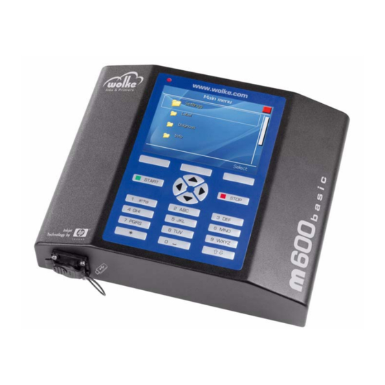
- Page 1 Manual m600 basic English Version 2.6_01 Updated 30.05.2012...
- Page 3 Operating Manual English Manual m600 basic Version: 2.6_01 Updated: 30.05.2012 It is essential that you read this operating manual before commis- sioning! Please observe the safety instructions! Keep in a safe place for future reference. Neither this documentation or any of the documents in the appendix...
-
Page 5: Table Of Contents
Installation ........5 Integral parts and accessories of the m600 basic Controller 4.2.1... - Page 6 Diagnosis........134 Start diagnosis 8.1.1 Print head 1/2 Inputs and Outputs 8.2.1 Inputs 8.2.2 Outputs Manual m600 basic 2.6_01...
- Page 7 Maintenance instructions m600 basic data sheet ......178 Declaration of Conformity ......179 FAQ .
- Page 8 Contents Manual m600 basic 2.6_01...
- Page 9 Connection example Signal light with 5 meter I/O cable ..173 Tab. 14_22: Pin assignment of the photoelectric cell..... . 175 Manual m600 basic 2.6_01...
- Page 11 Print head positioning options ......15 Fig. 4_29: Examples – equipment of the m600 basic with two print heads ..15 Fig. 4_30: Printing head according to the number of print heads .
- Page 12 External input 3 ........54 VIII Manual m600 basic 2.6_01...
- Page 13 Barcode – Value ........81 Manual m600 basic 2.6_01...
- Page 14 Counter – Number of digits .......105 Manual m600 basic 2.6_01...
- Page 15 Label parameter – Cyclic ....... . . 127 Manual m600 basic 2.6_01...
- Page 16 ....... . . 170 Fig. 14_245: Wiring example for the 24 V DC interface .....174 Manual m600 basic 2.6_01...
- Page 17 Information which, if not observed, may result in a health hazard for the operator. INFORMATION ON CARE This symbol indicates important information about how to care for the m600 basic correctly. Non-observance of this information may result in faults in the operation of the m600 basic or its environment.
-
Page 19: Identification
Ostbahnstraße 116 D-91217 Hersbruck www.wolke.com Intended use The m600 basic is exclusively intended for the coding of various materials Intended use (products, packaging materials, etc.). The customer is to ensure that the inks are used appropriately. Any use other than or exceeding the scope described above shall be con- sidered as improper use. -
Page 20: General Instructions And Information
• Improper installation, commissioning, operation and maintenance of the m600 basic. • Operation of the m600 basic with faulty safety devices or improperly fitted/ non-functional safety or protective devices. • Non-compliance with instructions in the operating manual relating to trans- portation, storage, installation, commissioning, operation, maintenance and setting up of the m600 basic. -
Page 21: Safety Instructions
• Those regular checks are conducted to ensure that they work safely. Duties of the staff • All persons instructed to work on the m600 basic agree to comply with the Duties of the following requirements before starting their work: staff •... -
Page 22: Hazards Associated With Handling The M600 Basic
Safety instructions Hazards associated with handling the m600 basic The m600 basic has been designed in accordance with the state of the art Hazards associated with in technology and approved safety practice. Nevertheless, there is still a handling the risk of certain dangers to the life and health of the operator or third party... -
Page 23: Installation
Installation Installation Integral parts and accessories of the m600 basic Scope of supplies: Main compo- nents Remove all parts from the cardboard box and remove the packaging material. (Avoid damaging the components when using sharp objects to open the packaging.) ... -
Page 24: Fig. 4_3: Connector Cable From Print Head To The Controller; One Cable/Print Head
Fig. 4_5: Sensor The adapter plate and the spacer plate are required if the locating wheel is used, for mounting the sen- sor to the print head. Fig. 4_6: Adapter plate (left-hand) and spacer plate Manual m600 basic 2.6_01... -
Page 25: Fig. 4_8: Hp Cartridge
Fig. 4_10: Mounting kit for 1-head mounting The accessory part for multi-head mounting is suitable for all print head versions. The adjusting unit allows the print heads to be finely adjusted for perfect print images. Fig. 4_11: Adjusting unit for multi-head mounting Manual m600 basic 2.6_01... -
Page 26: Fig. 4_12: Parallelogram With Locating Wheel
Either the locating wheel or the deflector are used depending on the specific application. Fig. 4_13: Deflector and locating wheel The pulse generator is for measur- ing the product speed and therefore for adjusting the print to different speeds. Fig. 4_14: Pulse generator Manual m600 basic 2.6_01... -
Page 27: Fig. 4_15: Measuring Wheels For Pulse Generator
Fig. 4_17: Pulse generator cable Accessories The warning beacon is mounted di- rectly on the m600 basic and is for indicating system faults. (for hard- ware version m1.21) Fig. 4_18: Warning beacon This simulation box is for internal... -
Page 28: Controller
Alternatively, it can also be mounted vertically, for which the four threaded holes (M6) on the underside of the controller are provided. ATTENTION Only use screws with a maximum length of 12 mm. Screws which are any longer will damage the controller housing. Manual m600 basic 2.6_01... -
Page 29: Terminals
The controller comes with the following terminals on the back for instal- lation: Fig. 4_22: Rear of controller – connectivity On/Off switch Ethernet interface (optional) Fuse Terminals for print head cables Terminal for the pulse generator Power plug I/O Terminal 24 V DC Manual m600 basic 2.6_01... -
Page 30: Ip65 Caps On The Controller's Rear Side
Fig. 4_23: Rear of controller with caps ATTENTION Any damage resulting from IP65 caps which are not screw-fastened will not be covered by the guarantee/ warranty. Manual m600 basic 2.6_01... -
Page 31: Print Head And Hp Cartridge
Fig. 4_24: Standard print head (in this case with a conventional photoelectric cell) Connector cable for photoelectric Scraper plate cell - print head Terminal for connector cable for Original HP cartridge, print head - controller e. g. type 51645A Print head Photoelectric cell Optical fiber Manual m600 basic 2.6_01... -
Page 32: Fig. 4_25: Red Print Head
Special version, similar to the green print head, but with a side mount. Since it does not have the mounting lugs at the bottom, it can be inte- grated even deeper in the machine. Fig. 4_27: Golden print head Manual m600 basic 2.6_01... -
Page 33: Positioning Of Print Head
All on one side, left- 1 on the left and 1 on the hand hand right Side and at the top from top, left-hand from top, right-hand Fig. 4_29: Examples – equipment of the m600 basic with two print heads Manual m600 basic 2.6_01... -
Page 34: Installing The Print Heads
1 mm and max. 3 mm. The print head scraper plate can be directly in contact with the product and is intended to provide protection for the cartridge. Manual m600 basic 2.6_01... -
Page 35: Photoelectric Cell
To enable the photoelectric cell to be fitted, our print heads have been Photoelectric equipped with four new size M3 threads (two on each side, see below in cell Chapter 14.1, "Technical drawings"). Fig. 4_32: Photoelectric cell (Keyence) Manual m600 basic 2.6_01... -
Page 36: Position Of Photoelectric Cell
If the optical fiber is not cut cleanly, this may impair the operation of the photoelectric cell. Therefore: Only use each cutting hole in the cutter once. Every new optical fiber comes with a new cutter. Fig. 4_34: Cutter for optical fibre Manual m600 basic 2.6_01... -
Page 37: Fig. 4_35: Cutting The Optical Fiber To Size
Make sure that the optical fiber is aligned flush with the bottom of the head plate. Lock with the nut. Use the relevant hole in the head plate depending on the direction of printing! Manual m600 basic 2.6_01... - Page 38 Otherwise the sensor will not be able to issue the correct signal. Fasten the installation mount to the print head with the supplied screws and latch the photoelectric cell onto the installation mount! Manual m600 basic 2.6_01...
-
Page 39: Settings Of Photoelectric Cell
Stability indicator (green) Lights up when sufficient light is received. Indicator Shows the current position of the sensitivity trimmer. One turn of the trimmer changes the position of the indicator by one mark on the indicator scale. Manual m600 basic 2.6_01... -
Page 40: Detection Of A Measuring Object
Using a measuring object, set the sensitivity in the identification ar- ea. To do so, turn the trimmer in a clockwise direction until the func- tion indicator (red LED) lights up. This is point A. Manual m600 basic 2.6_01... - Page 41 Set the D.ON/L.ON switch in dependency on whether the sensor should be switched on or off for an object. NOTE After changing over the FINE/TURBO selector, sensitivity must be readjusted. Manual m600 basic 2.6_01...
-
Page 42: Pulse Generator (Optional)
Fig. 4_37: Pulse generator and rubber measuring wheel The m600 basic determines the speed information in two different ways: Measurement of the speed by means of pulse generator For optimum printing results it is necessary to have precise speed meas- urements. -
Page 43: Fig. 4_39: Various Measuring Wheel Versions
This mount enables the position and pressing pressure to be adjusted. Fig. 4_40: Resilient pulse generator mount NOTE Ideally you should avoid mounting the pulse generator on the belt shaft or on the underside of the conveyor belt. The speeds can well be different here. Manual m600 basic 2.6_01... -
Page 44: Installation By Means Of The Mounting System (Optional)
Fig. 4_43: Mounting adapter for green, red and gold colored print heads The mounting adapter for assembly of a golden print head is available in a length of 400 mm. Fig. 4_44: Mounting adapter for gold colored print heads Manual m600 basic 2.6_01... -
Page 45: Fig. 4_45: Example With Reference To 1-Head Mounting (Using A 1-Head Mounting System)
Fig. 4_47: Stainless steel mounting adapter for the blue print head The mounting adapter for assem- bly of a golden print head is avail- able in a length of 200 mm. Fig. 4_48: Stainless steel mounting adapter for the golden print head Manual m600 basic 2.6_01... -
Page 46: Installation By Means Of The Parallelogram (Optional)
It is suitable for side- or top-mounting. The maximum deflection is 90 mm, measured from the rest position. lateral, uneven/cam- lateral, different at the top bered products product positions packages Fig. 4_50: possible positions of the parallelogram Parallelogram Print head Manual m600 basic 2.6_01... - Page 47 M3 screws (6 mm long). Screw on the installation Attach and connect the Fasten adapter mount. sensor. spacer plate (two size M3 screws, max. 15 mm long). Manual m600 basic 2.6_01...
-
Page 48: Connecting The Printer Components
For further information on the positions of the print heads, please refer to Chapter 4.3.1! The following applies in general: The device must always be switched off before you undertake any work of con- necting or disconnecting. Manual m600 basic 2.6_01... -
Page 49: Operation
Button Function Menu-dependent: Back/Cancel/OK/C/YES/NO/Select/Activate/Display/ Change/Insert m600 basic controller is activated. A green square appears top right in the screen m600 basic controller is deactivated. A red square appears top right in the display Cursor control buttons to navigate within the menus .,?!1@'-_():;&/%*#+§\€~[]÷"... -
Page 50: Display
"Activate/Exe- Fig. 5_53: Main menu cute" to get to the appropriate menu. Status display m600 basic controller Scroll bar Selected menu item Menu button "Activate" m600 basic has been deactivated m600 basic has been activated Fig. 5_54: Main menu – continued... -
Page 51: Navigation
"Cancel", and exit selection Once you have edited all your desired menu items, press the "Back" key (= apply entry(ies) and exit the menu). Fields for user-defined editing, example: Fig. 5_56: Example – Fields for user-defined editing Manual m600 basic 2.6_01... -
Page 52: Fig. 5_57: Lists, Example 1
• Exit the list without selection via the menu button "Cancel" or actuate "OK" to accept the selection and exit list. • Actuate the menu button "Back" to exit the menu and change over to pre- vious menu display. Manual m600 basic 2.6_01... -
Page 53: Main Menu
Function to access quickly the preview of the current print label (see Chapter 10). Logon: Logon as user (see Chapter 11). File management Function to load and save files via USB stick or delete files on the flash disk (see Chapter 13). Manual m600 basic 2.6_01... -
Page 54: Settings
Settings regarding the pulse generator, specification of pulses / speed, settings regarding inputs / outputs and the arrangement of the print heads (see Chapter 6.2). Cartridge: Settings regarding the cartridge type, ink type, temperature control and the ink level alarm (see Chapter 6.3). Manual m600 basic 2.6_01... -
Page 55: Fig. 6_61: Main Menu > Settings > System
6.1.1) Time: Setting the system time of the m600 basic (see Chapter 6.1.2). Language: Here, the system language of the m600 basic is set (see Chapter 6.1.3). Network: Setting of the parameters for communication via Ethernet interface (see Chapter 6.1.4) -
Page 56: Date
Chapter 6.1.5). Screen saver: Activation/deactivation of the screen saver function (see Chapter 6.1.6) Factory settings: Here, the settings of the m600 basic are reset to the state as delivered (see Chapter 6.1.7). 6.1.1 Date System date Fig. 6_62: Settings > System > Date Changing the date: ... -
Page 57: Time
Tab. 6_2: Selection list "Menu language" Actuate the cursor buttons to select the menu "Language". Actuate the menu button "Select" to accept the required menu lan- guage of the m600 basic. Actuate OK to confirm the selection. Manual m600 basic 2.6_01... -
Page 58: Network
NOTE If the device name is deleted and no name assigned, "m600 basic" is entered automatically as device name when the menu is exited. Fig. 6_66: Network > Assigning a device name... -
Page 59: Fig. 6_67: Network > Autom. Network Address
IP address is for entering the static IP address to be used in your network for the m600 basic. The IP address to be entered here is dependent on the specific network in which the m600 basic is to be integrated. -
Page 60: Password
If no passwords are assigned, all users remain logged on with full access rights. NOTE A user should always be configured as an administrator (with all access rights). Manual m600 basic 2.6_01... -
Page 61: Fig. 6_70: Password > User > User1 > Rename
Confirm by pressing "OK". Now, the password has been assigned. Repeat this procedure for all other users. To exit the Logon menu, press the "Back" menu button. Repeat the same procedure for other users if you wish to assign or change their passwords. Manual m600 basic 2.6_01... -
Page 62: Fig. 6_72: User > User 1 > Access Rights
Each user can be assigned different access rights. However, only a user should be able to perform this assignment who has administrator status. All access rights are available under menu item "Releases". Fig. 6_72: User > User 1 > Access rights Manual m600 basic 2.6_01... - Page 63 (see Chapter 6.1.5). File management Enables files to be loaded and saved via USB stick or files to be deleted on the flash disk (see Chapter 13). Software update Performing a software update (see Chapter 13.3) Manual m600 basic 2.6_01...
-
Page 64: Fig. 6_73: User 1 > Access Rights > System Settings
Repeat this procedure if you wish to change other releases. Deleting a password: Delete pass- words Select "Delete passwords". Fig. 6_74: User1 > Delete passwords Select the user whose password is to be deleted, and actuate the function key "Delete". Manual m600 basic 2.6_01... -
Page 65: Screen Saver
6.1.6 Screen saver The m600 basic operating system has a "screen saver function" (similar Screen saver to that of a PC), to extend the service life of the backlight tube of the LCD display used in the m600 basic. -
Page 66: Factory Settings
Fig. 6_78: Autom. screen saver > Delay [min] Actuation of any key causes the m600 basic’s display lighting to be switched on without triggering any other function on the m600 basic. The display lighting is also switched on again whenever information, a warning or an error message appear. -
Page 67: Installation
Chapter 6.2.2). Print head1/2: Communicate activation of sensor for head1 or head2, text position, mir- roring, presence of a sensor and sensor distance (see Chapter 8.1.1). Spitting: Activation/deactivation of the automatic spitting process (see Chapter 6.2.5) Manual m600 basic 2.6_01... -
Page 68: Pulse Generator/Pulses/Speed
When the pulse generator input is activated, the pulses/m line is automat- ically made visible. Deactivation: If the pulse generator is not activated, the measured product speed in "m/min" can be entered in the field ("Speed [m/min]"). Fig. 6_82: Installation > Speed [m/min] Manual m600 basic 2.6_01... -
Page 69: Fig. 6_83: Installation > Pulses/M
Wheel diameter Pulses/m Solid aluminium, 67,33 mm 11.819 smooth (standard) Aluminium with studded 63,66 mm 12.500 rubber cover Solid aluminium with 63,66 mm 12.500 cross spokes Plastic, smooth 63,66 mm 12.500 Tab. 6_4: Pulse generator with dimensions Manual m600 basic 2.6_01... - Page 70 It is imperative that this calculation is made if an external pulse generator is used. The maximum permitted input frequency for the pulse generator input on the m600 basic is 30 kHz. This value must never be exceeded. ATTENTION If the speed is not constant, this may be indicated by the following: •...
-
Page 71: Input 1
Selecting "Activate m600 basic" means that input 1 can be used to acti- vate the m600 basic via an external signal (e. g. PLC). The function is trig- gered with a falling edge. The green "Start key" remains in operation. -
Page 72: Input 2
The effect of selecting "Start sensor" is that the external input 2 is evalu- ated for the trigger signal (start signal) for print head 2 instead of the pho- toelectric cell on print head 1. The m600 basic reacts to the rising edge. Deactivate m600 basic Selecting "Deactivate m600 basic"... -
Page 73: Fig. 6_88: External Input 4
Counter input Input 3 Input 3 can be used to increment the counter field in the m600 basic also via an external trigger (reacts to rising edge) by the preset step size (pal- let counter). In the counter menu, updating must be set to "Update exter- nal". -
Page 74: External Output 4
The menus in this input mask enable activation of the sensor for head1 or Print heads and print head con- head2 and the m600 basic to be informed about the position of the text, figuration possible mirroring, presence of a sensor and the sensor distance. -
Page 75: Fig. 6_91: Print Head 1 > Product Sensor
Print heads and print head con- figuration Fig. 6_92: Print head 1 > Mirrored OFF: Letters, normal Letters, upside down Reflected Fig. 6_93: Print head 1 > Reflected OFF: Letters, normal Letters, mirrored Manual m600 basic 2.6_01... -
Page 76: Fig. 6_94: Print Head 1 > Printing Direction
"Print heads" field (position, mirrored, print direction, sensor, sensor distance). NOTE In all the following descriptions, the direction information is based on position ("?"/"¿") facing the nozzle plates on the cartridges. Manual m600 basic 2.6_01... -
Page 77: Various System Settings
The factory setting is based on the following constellation: Various system settings Conveyor belt Photoelectric cell Print heads Fig. 6_96: Factory setting – Menu settings print head 1 and 2 Alternative A - Reverse product path direction Photoelectric cell Conveyor belt Print heads Manual m600 basic 2.6_01... -
Page 78: Fig. 6_97: Alternative A - Menu Settings Print Head 1 And 2
Fig. 6_97: Alternative A – Menu settings print head 1 and 2 Alternative B - Print direction as in the factory setting, read direction re- Various system settings versed Conveyor belt Photoelectric cell Print heads Fig. 6_98: Alternative B – Menu settings print head 1 and 2 Manual m600 basic 2.6_01... -
Page 79: Spitting
The spit parameters "Waiting time“ and "Spitting duration“ apply globally for each label. NOTE Spitting (automatic or manual) is only possible if the m600 basic is in start mode. The spit process is displayed on top left of the menu with a drop icon. Manual m600 basic 2.6_01... -
Page 80: Fig. 6_100: System > Spitting
The waiting time can be set in steps of 1 sec from 1 to 3600 seconds. The waiting time can be reset optionally by a signal of an external input, Chapter 6.2.2. Fig. 6_102: Spitting > Waiting time [s] Manual m600 basic 2.6_01... -
Page 81: Image Refresh
• The label settings decide whether spitting is effected with one or two print heads. 6.2.6 Image refresh This function enables the time and date fields to be updated automatically Image refresh in accordance with the set waiting time. Fig. 6_104: Installation > Image refresh Manual m600 basic 2.6_01... -
Page 82: Cartridge
For the waiting time (in seconds) to expire, a value between 0 and 600 Image refresh can be entered here. Fig. 6_106: Installation > Image refresh > Waiting time [s] Cartridge Here, the settings for the cartridges are made. Cartridge Fig. 6_107: Settings > Cartridge > Print head 1/2 Manual m600 basic 2.6_01... -
Page 83: Print Head 1/2
Activation/deactivation of the function "Temperature-controlled" (see Chapter 6.3.4). Cartridge size identical: Activation/deactivation "Cartridge size identical" (see Chapter 6.3.5). Alarm function: Activating the alarm function (see Chapter 6.3.6). Threshold: Entry of threshold for the alarm function (see Chapter 6.3.7). Manual m600 basic 2.6_01... -
Page 84: Cartridge Size - Type
The volume set here is used as the basis for calculating the ink con- sumption. To ensure that the correct level of ink is always shown and for the "Cartridge empty" signal, the setting must always correspond with the ink system used (cartridge or bulk). Manual m600 basic 2.6_01... -
Page 85: Ink Type
The suitability of a certain ink cannot be predicted pre- cisely, but must be determined by printing tests. Please ask your Wolke sales partner who will be pleased to do this for you. No warranty can be assumed for the use of an ink without printing tests. -
Page 86: Tab. 6_5: Ink Type
2 hours. INFORMATION ON CARE Our black fast-drying ink "Classic Duo" (Order No.: 660015) is always supplied with a bottle of cleaner with each unit pack (2 cartridges). Manual m600 basic 2.6_01... -
Page 87: Temperature-Controlled
ATTENTION We recommend that you consult your contact person at Wolke before ever deactivating the temperature control. 6.3.5 Cartridge size identical Cartridge size identical Fig. -
Page 88: Alarm Function
The message is triggered once the preset threshold is reached. Actuate the menu button "OK" to accept the value Enter "C" to de- lete the last en- try. Actuate "Can- cel" to exit the menu. Fig. 6_114: Cartridge > Print head 1 > Treshold Manual m600 basic 2.6_01... -
Page 89: Print Head 2
If a cartridge is removed from the print head during printing while the Cartridge temperature control is activated, or if printing is started without cartridge, removed the following message appears: Fig. 6_116: Message „Print head error“ Manual m600 basic 2.6_01... -
Page 90: Label
Size of a label: • maximum length of label: 500 mm • maximum height of label (one print head): 12.7 mm • maximum height of label (two print heads): 25.4 mm Manual m600 basic 2.6_01... -
Page 91: Fig. 7_118: 2-Head Label
The size of a field is defined via the font size and the volume of its contents (number of characters, size of bitmap, scaling of a barcode etc.). field 1 field 2 Fig. 7_118: 2-head label Manual m600 basic 2.6_01... -
Page 92: Field Types
Here, a date is generated automatically (best-before date, date of manu- facture, …) (see Chapter 7.3.4). Time: Inserting time, production time etc. (see Chapter 7.3.5). Counter: Inserting a counter (see Chapter 7.3.6). Shift: Here, the appropriate shift can be entered (see Chapter 7.3.7) Manual m600 basic 2.6_01... -
Page 93: Fig. 7_119: Edit > New Object > Text1
The text height is for the entered text/information. The font size can be set separately for every new line of text. The default value can be changed and every print height between 0.3 mm and 24 mm, with 2 print heads, can be selected in 0.1 mm increments. Manual m600 basic 2.6_01... -
Page 94: Fig. 7_121: Text Object - Entry Of Font Size
NOTE The entered text height is based on standard characters (e. g. H, I, R). However, since the m600 basic supports genuine descenders (e.g. j, g, { ), the text field is larger than the text height which is entered. Standard charac- ters (e.g. -
Page 95: Fig. 7_123: Text Object - Definition Y Position
"Yes" to ac- knowledge de- leting of the object. To exit the menu, actuate the menu but- ton "No". Fig. 7_124: Delete text object You can add further objects via the folder "New object". Manual m600 basic 2.6_01... -
Page 96: Bitmap
• Resolution of 600 x 600 dpi • The bitmaps are not scaled, i.e. they cannot be varied in size in the m600 basic, as can e. g. texts or barcodes. • If a bitmap has a resolution of 300 x 300 dpi, the printed bitmap only has half the width and half the height of the original bitmap. -
Page 97: Barcodes
To this effect, it is recommended to perform some test prints to judge the behaviour. To print barcodes of the required quality, the m600 basic requires a pre- cise speed signal. If the speed signal is wrong, the barcode is either compressed, stretched or printed with tailing, which necessarily impairs the reading effect. -
Page 98: Ean13/Ean8
Select "Barcode" as new object. Fig. 7_127: New object barcode Select the required barcode type in the menu "Type". Fig. 7_128: Selection of barcode Determine the barcode parameters. Fig. 7_129: Determination of the barcode parameters Manual m600 basic 2.6_01... -
Page 99: Fig. 7_130: Barcode Parameters - Continued
To provide a barcode with an embedded field (e.g. date or counter), pro- ceed as follows: Call up "Value" in conjunction with a barcode. Actuate the asterisk button. Now, the displayed embedded fields are available: Manual m600 basic 2.6_01... -
Page 100: Fig. 7_132: Barcode - Embedded Fields
"Height" is for setting the print height of the barcode. Fig. 7_133: Determining height of barcode Scaling The "Scaling" function is for expanding or compressing the barcode so that it can be adjusted to meet requirements. Fig. 7_134: Barcode – Scaling Manual m600 basic 2.6_01... -
Page 101: Fig. 7_135: Barcode - Bar Width Reduction
Leave the value unchanged first and then decide after the first test print whether an adjustment is required. Fig. 7_135: Barcode – Bar width reduction Reduktion: 0 Pixel Reduktion: 4 Pixel Skalierung: 120% Skalierung: 120% Fig. 7_136: Patterns with identical scaling and different reduction Manual m600 basic 2.6_01... -
Page 102: Fig. 7_137: Example - Barcode With And Without Numerical Plain Text Line
This is for specifying whether the barcode appears with or without a number plain text line. Fig. 7_137: Example - barcode with and without numerical plain text line Fig. 7_138: Activation/deactivation of plain text line Manual m600 basic 2.6_01... -
Page 103: Upc-A
Fig. 7_139: Barcode – Type UPC-A Value This is for entering the 11 digits for a UPC-A. The last digit = check digit does not have to be entered manually because it is calculated by the pro- gram itself. Manual m600 basic 2.6_01... -
Page 104: Code128/Ean128
Chapter 7.3.1, "Text". For explanations relating to the menu items marked , please refer to Chapter 7.3.3, "Barcodes". Fig. 7_140: Barcode – Type EAN128/Code128 Manual m600 basic 2.6_01... -
Page 105: Fig. 7_141: Determination Of Text Position
The distance function is for specifying the distance between the barcode and the plain text line. Text space 1,5 mm Text space 0,5 mm Fig. 7_142: Barcode – Defining the distance Font size [mm] This defines the height of the text in the plain text line. Manual m600 basic 2.6_01... -
Page 106: 2/5I
Chapter 7.3.1, "Text". For explanations relating to the menu items marked , please refer to Chapter 7.3.3, "Barcodes". Fig. 7_143: Barcode – Type 2/5i Manual m600 basic 2.6_01... -
Page 107: Fig. 7_144: Activation/Deactivation Of Check Digit Calculation
Bar ratio is for specifying the ratio between thick and thin barcode bars. The value entered here should be between 200 % and 300 %. Example prints: Bar ratio 200 Bar ratio 300 Fig. 7_145: Barcode – Ratio Manual m600 basic 2.6_01... -
Page 108: Code39
Fig. 7_146: Example print Code39 Given that the menu fields for Code39 are the same as the fields for the previous barcodes, please refer to the previous pages for explanations. Fig. 7_147: Barcode – Type Code39 Manual m600 basic 2.6_01... -
Page 109: Datamatrix
This field is for entering the characters in the Datamatrix code. The code is later shown in the display in the form of a square/rectangular (depending on the matrix selected). The matrix size is directly dependent on the number of characters entered here! Manual m600 basic 2.6_01... -
Page 110: Tab. 7_6: Gs1 Application Identifier - Excerpt
Label ATTENTION All size specifications in relation to the 2D Datamatrix code are based on a m600 basic's resolution of 600 x 600 dpi. Excerpt from the list of GS1 Application Identifiers (AI) available: Datamatrix Complete designation Format GTIN n2+n14 Lot/batch number n2+an..20... -
Page 111: Fig. 7_149: Drawing For The Datamatrix
10 x 10 pixels. If, for example, the m600 basic is set to “Left nozzle row” (= 300 dpi vertical resolution) and a resolution in the printing direction (= e. -
Page 112: Fig. 7_150: Example Datamatrix
Bar width reduction, crosswise An entry in this field reduces the number of pixels in each module crosswise to the direction of printing. The size of the Datamatrix code is not affected by these two entries. Manual m600 basic 2.6_01... -
Page 113: Date
The example date of "3/7/2008" was selected at random; in the print field the date is displayed on the basis of the date of the day. Manual m600 basic 2.6_01... -
Page 114: Tab. 7_8: Format Parameters In The Date Field
Tab. 7_8: Format parameters in the date field Lead (Days, Months, Years) If instead of printing the date of the day you wish to print a date which is after that date, the number of days/months/years offset has to be entered here. Manual m600 basic 2.6_01... -
Page 115: Fig. 7_153: Date - Lead
Fig. 7_155: Date – Offset (Minute) Offset (Hour) If instead of having the date adjusted at midnight on the selected day you wish to choose a different time, you can enter this time in hours here. Manual m600 basic 2.6_01... -
Page 116: Fig. 7_156: Date - Offset (Hour)
Fig. 7_157: Date – Update Interval This is for specifying the interval between the monthly or yearly updates. Fig. 7_158: Date – Interval, update weekly Manual m600 basic 2.6_01... -
Page 117: Tab. 7_9: Examples For Update Mode And Intervals
2 = second day of the month 15 = 15th day of the month 31 = 31th day of the month Note: The m600 basic always inter- prets the 31st day as the last day of the month. If the user has entered "31" under "in- terval", updating takes place... -
Page 118: Fig. 7_160: Date - Font Size
Label Fig. 7_160: Date – Font size Fig. 7_161: Date – X position Date Fig. 7_162: Date – Y position Fig. 7_163: Delete date field Manual m600 basic 2.6_01... -
Page 119: Time
"in- dividual". The time integrated in the selection list is selected as an example. The time format is displayed in the label field on the basis of the current time. Fig. 7_165: Time – Templates Manual m600 basic 2.6_01... -
Page 120: Tab. 7_10: Format Parameters In The Time Field
Time Fig. 7_166: Time – individual For an explanation on the menu items Font size [mm], X position [mm], Y position [mm] and Delete object, please refer to Chapter 7.3.1. Fig. 7_167: Time – Font size Manual m600 basic 2.6_01... -
Page 121: Fig. 7_168: Time - X Position
Label Fig. 7_168: Time – X position Time Fig. 7_169: Time – Y position Fig. 7_170: Delete time field Manual m600 basic 2.6_01... -
Page 122: Counter
This menu is for setting up counters (e. g. batch numbers). Counter Fig. 7_171: New object counter Counter status "Counter status" defines the starting value for the counter. Enter the value without sign. Fig. 7_172: Counter status Manual m600 basic 2.6_01... -
Page 123: Fig. 7_173: Counter - Start Value
You can also enter more digits than the counter value actually has, and fill up the rest with “0”. To this effect, however, the selection "Leading zeros" must be activated. Fig. 7_175: Counter – Number of digits Manual m600 basic 2.6_01... -
Page 124: Fig. 7_176: Counter - Step Size
The first product batch is comprised of 50 packages: Number of batches: 50 The first 50 packages will be printed with the same counter value (=batch number). Then the counter is increased by the set step size (see previous counter menu view). Manual m600 basic 2.6_01... -
Page 125: Fig. 7_178: Counter - Batch Number
Therefore, 10 is entered in "Batch start value" and 50 in "Number of batches" (applicable for all subsequent batches). Fig. 7_179: Counter – Start values of series Update Fig. 7_180: Counter – Update Manual m600 basic 2.6_01... -
Page 126: Fig. 7_181: Actualization Behaviour - Update Per Print
Photoelectric cell pulse Update external (counter field with external trigger = pallet counter) The counter in the m600 basic can also be incremented via an external trigger by the preset step size. The external inputs must be configured ac- cordingly (see Chapter 6.2.2). -
Page 127: Fig. 7_183: Counter - Final Value Reached
For an explanation on the menu items Font size [mm], X position [mm], Y position [mm] and Delete object, please refer to Chapter 7.3.1, "Text". Fig. 7_184: Counter – Font size Fig. 7_185: Counter – X position Manual m600 basic 2.6_01... -
Page 128: Shift
Label Fig. 7_186: Counter – Y position Counter Fig. 7_187: Delete counter 7.3.7 Shift Shift Fig. 7_188: New object Shift Manual m600 basic 2.6_01... -
Page 129: Fig. 7_189: Number Of Shifts
The only time entered for each shift is the time at which the shift begins. The duration of the shift is derived automatically from the start of the next shift. Fig. 7_190: Beginning of shift Manual m600 basic 2.6_01... -
Page 130: Fig. 7_191: Shift Name
You can repeat this approach for each activated shift. Shift For an explanation on the menu items Font size [mm], X position [mm], Y position [mm] and Delete object, please refer to Chapter 7.3.1, "Text". Fig. 7_192: Shift - font size Manual m600 basic 2.6_01... -
Page 131: Fig. 7_193: Shift - X Position
Label Fig. 7_193: Shift - X position Shift Fig. 7_194: Shift - Y position Fig. 7_195: Delete shift Manual m600 basic 2.6_01... -
Page 132: Creating A Label
Assign a suitable file name. Fig. 7_197: Example – Template 1Head After entering the file name, acknowledge by "OK". Fig. 7_198: Preview Demo1 The preview is still empty as no object has been inserted so far. Manual m600 basic 2.6_01... -
Page 133: Fig. 7_199: Edit Demo1
Accept the selection via the menu button "Activate". Fig. 7_199: Edit Demo1 Select "New object" via the arrow keys. Select the required object. Creating a label Fig. 7_200: Demo1 -New object Regarding the further approach, see Chapter 7.3.1 Chapter 7.6. Manual m600 basic 2.6_01... -
Page 134: Label Settings
The "Save as" menu opens to show this label under a new name, with the label settings and contents of the previously opened la- bel being retained. The contents of the label can now be edited or modified. Manual m600 basic 2.6_01... -
Page 135: Font
One print head corresponds to one print field. The label can be user-de- signed within this print field. Only the maximum print heights are prede- fined. 1 print head max. print height 12.7 mm 2 print heads max. print height 25.4 mm Manual m600 basic 2.6_01... -
Page 136: Fig. 7_204: Size & Resolution - Number Of Print Heads
"Number of print heads". ATTENTION The settings under "Label dimensions" still have to be en- tered separately for each of the print heads (see Chapter 7.5.3). Manual m600 basic 2.6_01... -
Page 137: Fig. 7_206: Size & Resolution - Nozzle Rows
With this setting you can choose between a vertical resolution of 300 dpi and 600 dpi. This has an influence on the density value of the printed text and therefore the ink consumption of the m600 basic. ATTENTION With a single nozzle row, the printed text is printed ver- tically with 300 dpi, and with two nozzle rows, it is printed with 600 dpi. -
Page 138: Tab. 7_11: Resolution And Max. Speed Of The Product
120 m/min. 400 feet/min. 120 dpi 150 m/min. 500 feet/min. 100 dpi 180 m/min. 600 feet/min. 75 dpi 240 m/min. 800 feet/min. 60 dpi 300 m/min. 1000 feet/min. Tab. 7_11: Resolution and max. speed of the product Manual m600 basic 2.6_01... -
Page 139: Tab. 7_12: Setting The „Distance After" Regarding The Speed And Data Volume
200, 240, 300, 360, 450 or 600 dpi. Performance of m600 basic and setting the "Distance after" The m600 basic has been designed for medium-duty industrial printer ap- plications (regarding speed and data content). For an optimum print per- formance, Wolke Inks & Printers GmbH recommends the following... -
Page 140: Label Size
This part of the menu is for setting the three dimensions which determine the length of the label (specifications in mm): Recognition of a new product Distance before Product Print length Recognition of the product by the Distance after photoelectric cell Manual m600 basic 2.6_01... -
Page 141: Fig. 7_211: Head 1 - Distance Before
Measure the text masters or the carton and enter the length of the label (in mm). This ensures that the label master is created with the correctly set length. Fig. 7_212: Head 1 – Print length Manual m600 basic 2.6_01... -
Page 142: Fig. 7_213: Head 1 - Distance After
2000 mm is possible. Label size Fig. 7_213: Head 1 – Distance after Print heads Product Photoelectric cell Distance after Print length Distance before NOTE For system-related reasons the "Distance after" must not be less than 5 mm. Manual m600 basic 2.6_01... -
Page 143: Other Parameters
Fig. 7_214: Label size – Label parameters Autostart After switching the m600 basic ON, the last label loaded is printed auto- matically (which has activated this parameter). Fig. 7_215: Label parameter – Autostart The "Autostart" function permits the m600 basic to be restarted automat- ically after a power failure. -
Page 144: Fig. 7_216: Label Parameter - Limited Output
(see next section). The counter does not appear on the print label; the function only counts the number of triggered prints. Printing stops when the end value has been reached. The status of the m600 basic changes over to "STOP". Other parameters Fig. -
Page 145: Fig. 7_218: Photoelectric Cell Pulse, E.g. Caused By A Carton Edge
Print material, e. g. cartons If you activate the "Cyclic" function you can manually enter the number of print cycles to be carried out for a single trigger of the photoelectric cell. Fig. 7_219: Label parameter – Cyclic Manual m600 basic 2.6_01... -
Page 146: Fig. 7_220: Photoelectric Cell Pulse, E.g. Caused By A Paper Edge
Print material, e. g. cartons Distance after Photoelectric cell Distance before Print head Photoelectric cell pulse, e.g. caused by printmarks NOTE This is the ideal setting if, for example, cartons have to be printed several times for certainty. Manual m600 basic 2.6_01... -
Page 147: Example - Creating A Straightforward Label
The following label is to be created as a straightforward example: Example - creating a straight- forward label "New" is selected to create a new label. A template with one print head is selected. Acknowledge via the button "Select". Manual m600 basic 2.6_01... - Page 148 "Demo2" and acknow- ledge by pressing "OK". Change over to menu "Edit" . Select "New object" and subsequently "Text". Example - creating a straight- forward label Enter the text "Demo2" and acknowledge pressing "OK"! Manual m600 basic 2.6_01...
- Page 149 The menu buttons + and - can be pressed to scale the view up or down accordingly in the preview. Now, the settings for the label as such (… > Demo2 > Editor > Settings > Label) must be made. The font "Arial" is used. Manual m600 basic 2.6_01...
- Page 150 On exiting the menu, you are again prompted to save. Example - creating a straight- Confirm also with "Yes". forward label Now, the label can be loaded. Pressing the "Start" button trig- gers printing of the label. Manual m600 basic 2.6_01...
-
Page 151: Loading And Printing Label File
Select "Load" and acknowledge the selection via the menu button "Select". On loading a label, the preview appears in terms of confir- mation. Now the label has been loaded. To print, actuate the "START" button. "Info" informs you which label is currently selected. Manual m600 basic 2.6_01... -
Page 152: Diagnosis
Fig. 8_225: Main menu – Diagnosis Start diagnosis To start the diagnosis for print head 1 or 2, a label must have been loaded Start diagnosis and the "Start" button must be actuated. Fig. 8_226: Diagnosis > Start diagnosis Manual m600 basic 2.6_01... -
Page 153: Print Head 1/2
It should be noted that only the number of print heads set in the menu "Settings/Label" is checked here. This message also appears if you have loaded a two-head label but only connected one head. Fig. 8_227: Diagnosis Print head 1 Manual m600 basic 2.6_01... - Page 154 For example, it is not possible to show nozzles which have dried out on the outside because a cartridge was incorrectly inserted. PEN ID The identification number for HP cartridges. This number is only of rele- vance for service personnel. Manual m600 basic 2.6_01...
-
Page 155: Inputs And Outputs
In addition to the inputs for the two photoelectric cells on the two print Inputs heads, the m600 basic also comes with four additional parameterizable digital inputs. These four inputs come out at the 24 V I/O socket. Fig. 8_228: Start diagnosis > Inputs 8.2.2... -
Page 156: Product Sensor (Ps)/Encoder
The current capacity utilization displays the current capacity utilization of the CPU in percent. The display is updated after each print. The longer the computing time required for accomplishing current printing processes, the higher the CPU capacity utilization. Manual m600 basic 2.6_01... -
Page 157: Replace Cartridge
When the m600 basic is commissioned for the first time the system menu is already preset for the use of full cartridges or bulk systems. The m600 basic ink counter has to be reset for the first time after the cartridges/bulk systems are replaced for the first time. -
Page 158: Status Displays Of The Warning Beacon
Status displays of the warning beacon The external outputs 1-3 are evaluated. Status displays of the warning beacon m600 basic is OFF or set m600 basic ready for printing Ink alarm to "STOP" m600 basic error Fig. 8_233: Various indications of the warning beacon... -
Page 159: Info
Fig. 9_234: Main menu > Info m600B version: Indicates the current software version. Hardware: Indicates manufacturer-specific information. Free memory: Displays the free RAM memory available (main memory) Current label: Indicates the currently loaded label. Current user: Indicates the current user. Manual m600 basic 2.6_01... -
Page 160: Show Current Print Label
The menu buttons + and - can be pressed to scale the view up or down label accordingly. As standard, the complete label is displayed. Fig. 10_235: Main menu > Show current print label Manual m600 basic 2.6_01... -
Page 161: Logon
Actuate the cursor buttons to select the required user group. Accept the selection via the menu button "Select". Actuate OK to confirm the selection. Enter the new password. Confirm by pressing "OK". Now, you are logged on. The main menu re-appears. Manual m600 basic 2.6_01... -
Page 162: Replacement Of Cartridge
When inserting the HP cartridge into the print heads, proceed as follows: Inserting the HP cartridge Deactivate the m600 basic (STOP key). For new HP cartridges, remove the protective tape from the gold contactor and nozzle plate, or for cartridges already in use, remove the cap. - Page 163 Always make sure that the cartridge is dry before you re- insert it. Do not use solvent-containing cleaning agents. Our black fast-drying ink (ref. no. 660015) is supplied with a bottle of cleaner with each unit pack (2 cartridges). Manual m600 basic 2.6_01...
-
Page 164: Data Exchange
Otherwise, the LAN module of the m600 basic may be damaged. Insert the stick in the USB port at the front of the m600 basic. In the main menu, select "File management" to load files to the m600 basic, to save them to another stick or to delete files from the flash disk. -
Page 165: Fig. 13_238: Standard Folders On The Usb Stick
Label templates for 1- m600bl Folder contains labels and 2-head labels m600ba Link update.bat File to execute the updates Manual m600 basic 2.6_01... -
Page 166: Loading Files
In the menu "Loading", the data located in the folder "m600Backup" on Loading files the USB stick are displayed in folders depending on the group in question (labels, fonts, bitmaps, etc.). Fig. 13_241: Loading files After loading, the message "File loaded" appears for confirmation. Manual m600 basic 2.6_01... - Page 167 6.1.4). Standard folders are used as subfolders. Labels Loading all or individual labels via USB stick Loading files Bitmaps Loading all or individual bitmaps via USB stick Fonts Loading all or individual fonts via USB stick Manual m600 basic 2.6_01...
- Page 168 Configuration Loading files Loading the installation configuration via USB stick. This can be transferred to another m600 basic. NOTE After a configuration has been loaded, the system is restarted once the menu is exited.
- Page 169 The function Loading > complete is used to perform an update. Loading files from another data backup: Insert the stick in the USB port at the front of the m600 basic. Select "Loading" in the main menu "File management" > to load the files onto the m600 basic! ...
-
Page 170: Backup Of Files
Select the required data backup via the arrow keys! Load the required files from the USB stick onto the m600 basic! 13.1.2 Backup of files In the function "Backup", backup of the data in question, which are on the... -
Page 171: Data Exchange Via Host Computer
Data exchange 13.2 Data exchange via host computer As of firmware version 0.1.5 of the m600 basic, a network link can be es- Data exchange via host tablished between a computer and the m600 basic. Thus, labels created computer on the m600 basic can be saved, and labels (created on the Label Desig- ner) and bitmaps can be transferred to the m600 basic. - Page 172 Classic/Advanced, i. e., black-and-white Windows bitmaps. Description of the folders - fonts The fonts which are at present on the m600 basic appear in the "Fonts" folder. The fonts are saved in the m600 basic's own format ".wft". Manual m600 basic 2.6_01...
- Page 173 • The overall length (distance before = 400 mm, print length = 500 mm and distance after = 2000 mm) must not exceed 2900 mm. • The labels must have a header of 11 (firmware Classic version 3.83 - 3.86). Manual m600 basic 2.6_01...
-
Page 174: Restrictions Of The Functions Of The Label Designer
The following restrictions apply for the m600 basic: • The label should be created on the m600 basic and subsequently be transferred to a PC via USB stick to be edited using the Label-Designer. • The label version must be compatible with the m600 (firmware Classic Version 3.83 - 3.86). -
Page 175: Software-Update
USB socket. This is due to the design of the mounting frame of the USB socket which must comply with protection class IP65 re- quirements. Performing an update of the m600 basic using a new software version: ATTENTION To execute an update, the access right must have been enabled by the administrator. - Page 176 Select the menu item "Complete"! Software update The following message appears: Confirm with the function button "Yes". You are asked to wait. After the update has been performed successfully, the m600 basic is shut down and restarted automatically. Manual m600 basic 2.6_01...
- Page 177 Data exchange NOTE If the following message appears after the update, the m600 basic must be shut off and restarted after 10 seconds. The m600 basic is restarted. NOTE If the following message appears after the restart, the m600 basic must be shut off and restarted after 10 seconds (version-dependent).
- Page 178 If the following message appears after the update, the user authorizations must be checked. Activate additionally the function "Log on for start" for one user and log on to the m600 basic with the user in question. Software- Update ...
-
Page 179: Technical Drawings
Technical data Technical data 14.1 Technical drawings Print head, blue Technical drawings Print head, red Manual m600 basic 2.6_01... - Page 180 Technical data Print head, green Technical drawings Print head, gold Manual m600 basic 2.6_01...
- Page 181 Technical data New sensor Technical drawings Sensor with installation mount Manual m600 basic 2.6_01...
- Page 182 Technical data Adapter plate for new sensor Technical drawings Spacer plate for new sensor, for use with a locating wheel Manual m600 basic 2.6_01...
- Page 183 Technical data Controller Technical drawings Manual m600 basic 2.6_01...
- Page 184 Technical data Parallelogram Manual m600 basic 2.6_01...
-
Page 185: Terminals
14.2.1 Power supply Supply voltage Power supply The user is not required to change the supply voltage. The m600 basic is adjusted automatically to the available supply voltage. However, the power plugs of usual local design must be used. Value... -
Page 186: Tab. 14_15: Connector Pin Assignment - Pulse Generator Socket
The output signal of the pulse generator must be a rectangular pulse sig- nal. This signal input on the m600 basic is equipped with a pullup resistor against +5V. It is sufficient if the primary detector can only drive the out- put signal actively to ground (0 Volt = "Low level") (open collector out-... -
Page 187: Fig. 14_243: Output Signal Profile Of Pulse Generator
Incorrect pulses per meter ratio set on the m600 basic If the ratio of pulses per meter set on the m600 basic identical to the ac- tual situation (e. g. a different pulse generator wheel, pulse generator wheel is not in direct contact with the belt, different pulse generator), the print image will either be stretched or compressed lengthwise. -
Page 188: Fig. 14_244: External Circuitry For Shaft Encoder Of Other Manufacturers With
If the speed of the belt is too slow the m600 basic interprets this as a stop. For very slow belt speeds it is therefore advisable to use a pulse generator with a large pulse/revolu- tion ratio. -
Page 189: Pulse Generator Extension Cables
14.2.3 Pulse generator extension cables Since the standard pulse generator is only supplied with a 3 m connecting Pulse generator cable, Wolke Inks & Printers GmbH also offers a range of extension cables extension cables in different lengths. Plug-and-socket connectors used A 12-pole plug-and-socket connector is used for the pulse generator con- nection. -
Page 190: External Inputs And Outputs
External inputs and outputs The m600 basic has 4 digital inputs and outputs. The inputs can be used to trigger a diversity of m600 basic functions. The outputs indicate various items of information about the status of the m600 basic. The relevant set- tings have to be made in the "Settings/System configuration/Ext. -
Page 191: Tab. 14_19: Limits For The 24 V Input Interface
The time given in the table refers to the use of the input as a signal for the start of printing. 24 V DC socket U out int Output voltage of the m600 basic driver 24 V DC V out ext. max. external voltage for power supply 50 V DC to the m600 basic power driver I out max. -
Page 192: Fig. 14_245: Wiring Example For The 24 V Dc Interface
Technical data Fig. 14_245: Wiring example for the 24 V DC interface Manual m600 basic 2.6_01... -
Page 193: Print Head Socket
(0 Volt) in the active state. Given that in the m600 basic, this signal is connected internally to a pullup resistor against +5 Volt, the signal level received by the m600 basic is ei- ther 0 Volt (active) or +5V (inactive). -
Page 194: Service And Maintenance
Dust on the contact pins of the print head can be evacu- ated using a vacuum pump or be removed with a fine paintbrush. To this effect, the m600 basic must be switched off! 15.2 Storage of ink cartridges The ink cartridges should be stored at room temperature (ambient tem-... -
Page 195: Maintenance Instructions
Check all screw-fastened plug-and-socket If necessary, retighten them. connectors for tight fit. Check quarterly the print head calbes in the If necessary, replace the print head cables. cable carriers for visible chafing, wear or crushed areas. Manual m600 basic 2.6_01... -
Page 196: M600 Basic Data Sheet
One copy is retained by your field service contact and another copy is re- tained by the Technical Support team at Wolke. This ensures that we can gain a quick overview of the system at the customer's and therefore offer better assistance whenever it is required. -
Page 197: Declaration Of Conformity
Data sheet m600 basic Wolke Inks & Printers GmbH - Ostbahnstr. 116 - D-91217 Hersbruck Support: http://www.wolke.com Company: Printer location Date: Delivered to: m600 basic serial number: Phone: Instruction by: Staff instructed: System settings Settings System Language Settings ... - Page 198 Settings Installation Print head 1 Print head 1 Sensor Reflected Mirrored Printing direction Sensor distance Fotozelle/ ext.Sensor LO Nr.: left-hand > right-hand __mm right-hand -> left-hand ...
-
Page 199: Label
Print head arrangement printing from above, top view printing laterally, side view Label settings Label Label name Edit Settings Label name .lbl Label dimensions Font Print head Distance before Print length Distance after Size &... - Page 200 User administration Settings System Password User 1 Name: System settings Installation settings Cartridge settings Select label Edit label Delete label Start diagnosis Reset cartridge...
- Page 201 Data sheet m600 basic Wolke Inks & Printers GmbH - Ostbahnstr. 116 - D-91217 Hersbruck Support: http://www.wolke.com Company: Printer location Date: Delivered to: m600 basic serial number: Phone: Instruction by: Staff instructed: System settings Settings System Language Settings ...
- Page 202 Settings Installation Print head 1 Print head 1 Sensor Reflected Mirrored Printing direction Sensor distance Fotozelle/ ext.Sensor LO Nr.: left-hand > right-hand __mm right-hand -> left-hand ...
- Page 203 Print head arrangement printing from above, top view printing laterally, side view Label settings Label Label name Edit Settings Label name .lbl Label dimensions Font Print head Distance before Print length Distance after Size &...
- Page 204 User administration Settings System Password User 1 Name: System settings Installation settings Cartridge settings Select label Edit label Delete label Start diagnosis Reset cartridge...
- Page 205 Declaration of Conformity Declaration of Conformity Declaration of Conformity Manual m600 basic 2.6_01...
-
Page 207: Faq
The label was not loaded. The label must be loaded before printing. The status of the m600 basic is In order to start printing the not on OK, i.e. the START key was START key has to be pressed. - Page 208 This has been correct- correspond to the external input ly connected to the I/O port at the in the "I/O" menu. back of the m600 basic but has Verify the settings in the menu not been correctly parameterized "I/O" of the m600 basic Chapter in the "External inputs"...
- Page 209 Some of the nozzles in the car- Replace the cartridge with a new tridge may be faulty as a result of one. Please do not forget to reset mechanical damage. the ink level in the "Change car- tridge" menu to 100 %. Manual m600 basic 2.6_01...
- Page 210 A counter field is printed in which Change the specifications for the number of prints the counter end value is prede- label. the m600 basic fined and the m600 basic witches automatically to STOP mode when this value is switches to reached. STOP.
-
Page 211: Spitting
The m600 basic is not set to OK. Spitting is only possible if the m600 basic is set to OK. 18.4... -
Page 212: Communication M600 Basic - Pc
The TCP/IP con- The cable connection between the Check the cable connection be- nection between m600 basic and the PC or the net- tween the m600 basic and the PC/ the m600 basic work has not been installed or has network. -
Page 213: Diagnosis
Fault Cause Solution diagnosis Speed informa- When the m600 basic is in the OK Run a print and watch the speed tion is not shown mode the diagnosis menu only indicator in the diagnosis menu. correctly shows the speed measured for the This is continuously updated dur- last successful print. -
Page 214: Screen Messages
The password of the user in question was deleted Wrong label version Label version (header) is wrong, label cannot be loaded, label was not created for the m600 basic; This message can also appear after an update and be cancelled by loading a label. - Page 215 This safety query appears if an object (e. g. a text field) delete the object / file? or a label is to be deleted. Manual m600 basic 2.6_01...
-
Page 217: Index
..... . . 98 Update ..... . 39 Language Manual m600 basic 2.6_01... - Page 218 ....188 Screen messages ..... 47 Screen saver Manual m600 basic 2.6_01...
Need help?
Do you have a question about the m600 basic and is the answer not in the manual?
Questions and answers