Sign In
Upload
Manuals
Brands
Wintriss Manuals
Control Systems
SmartPAC 2
Wintriss SmartPAC 2 Manuals
Manuals and User Guides for Wintriss SmartPAC 2. We have
2
Wintriss SmartPAC 2 manuals available for free PDF download: User Manual, Instruction Sheet
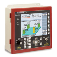
Wintriss SmartPAC 2 User Manual (604 pages)
Press Automation Control with WPC 2000 Clutch/Brake Control
Brand:
Wintriss
| Category:
Control Systems
| Size: 10 MB
Table of Contents
Table of Contents
7
Chapter 1. Introduction
29
WPC 2000 and Control Reliability
29
Smartpac 2 with WPC 2000
29
Smartpac 2 Standard Features
30
WPC 2000 Standard Features
30
Smartpac 2 Options
31
WPC 2000 Options
32
Resolver-Based Operation
34
Smartpac 2 Front Panel
34
Figure 1-1. Smartpac 2 Front Panel
35
WPC 2000 Operator Station
36
Figure 1-2. Operator Station Components (Side-Mounted Run/Inch Palm Buttons)
36
Smartpac 2 Settings
37
Sensors Available for Dipropac
38
Procampac Programmable Cams
39
Smartpac 2'S Three Modes of Operation
39
Smartpac 2 with WPC 2000 Specifications
40
Chapter 2. Installation
45
Installation Guidelines
47
Figure 2-1. Installation Overview
48
Connecting Wires to Terminal Block Connectors
49
Terminating Cable Shields
50
Figure 2-2. Correct Way to Attach Wires to Terminal Block Connectors
50
Figure 2-3. Connecting Shield Drain Wire to Ground Stud
50
Checking the Press
51
Installing WPC 2000
51
Mounting the Control Enclosure
51
Wiring the Control Enclosure
52
Figure 2-4. WPC 2000 Enclosure: Mounting Dimensions
52
Connecting AC Wiring
53
Figure 2-5. AC Input Wiring Connections
54
Installing WPC 2000 Without Enclosure
55
Figure 2-6. WPC 2000 Mounting Plate: Mounting Dimensions
55
Installing a Dual Safety Valve
56
Installing Air Pressure Sensors or Switches
57
Figure 2-7. Air Pressure Sensor
57
Table 2-1. Clutch Air Pressure Sensor Wiring Connections
58
Installing Operator Station(S)
60
Figure 2-8. Pre-Wired Operator Stations Showing Mute Lamp Connections
61
Figure 2-9. Wiring Steps to Modify Operator Station for WPC 2000
62
Figure 2-10. Pre-Wired Operator Station with Side Run Buttons: Mounting Dimensions
63
Figure 2-12. Unwired Operator Station: Mounting Dimensions
64
Wiring a User-Built Operator Station
65
Installing a Light Curtain
66
Installing the Resolver
68
Figure 2-13. Resolver: Mounting Dimensions
70
Table 2-4. WPC 2000 Resolver (TB 106) Wiring
71
Figure 2-14. WPC 2000 Main Processor Board: Location of Important Components
72
Installing the Overrun Limit Switch
73
Figure 2-15. Overrun Sensor Magnet Placement: Dwell as a Function of Shaft Diameter
74
Wiring WPC 2000 User Inputs
75
Table 2-6. WPC 2000 User Inputs: Stop Types, Fault Codes, and Wiring Connections
77
Connecting Other Wintriss Products to WPC 2000
78
Installing WPC 2000 Options
78
Wiring the Lockout Relay
78
Wiring Auxiliary Outputs
79
Wiring Operator Mode Outputs
81
Wiring a Foot Switch
82
Installing a One-Hand Control
83
Figure 2-18. One-Hand Control Switch: Mounting Dimensions
84
Figure 2-19. One-Hand Control Switch Base: Mounting Dimensions
85
Figure 2-20. Wiring Connections in One-Hand Control Switch (Switch Cover, Bottom View)
86
Wiring a Keylock Switch to Prevent Changes to WPC 2000 Settings
87
Installing Flywheel Speed Sensor
87
Mounting and Wiring the Bar Control Enclosure
88
Figure 2-22. Bar Control Enclosure: Mounting Dimensions
89
Wiring Automatic Single-Stroke
90
Wiring Automatic Continuous On-Demand
90
Installing Smartpac 2
91
Mounting the Smartpac 2 Control Enclosure
91
Installing Smartpac 2 as a Panel Mount
92
Figure 2-24. Smartpac 2 Mounting and Cutout Dimensions: Panel Mount
93
Wiring between WPC 2000 and Smartpac 2
94
Figure 2-25. Smartpac 2 Board: Location of Components
95
Table 2-16. Communications Wiring: Smartpac 2 to WPC 2000
96
Figure 2-26. Wiring AC to Terminal Block, Inside Enclosure, Top Right
97
Table 2-17. Stop and Input Check Circuit Wiring Connections
98
Connecting Smartpac 2 to a Network
99
Installing Smartpac 2 Options
100
Adding or Upgrading Dipropac or Procampac
100
Figure 2-28. Dipropac and Procampac Boards Installed on Smartpac 2 Board
101
Figure 2-29. Dipropac Boards (8-, 16-, and 32-Sensor): Location of Components
102
Connecting Dipro Sensor Interface to Smartpac 2
105
Wiring Diagrams
105
Table 2-19. Dipro Sensor Interface (DSI) 2 to Smartpac 2 Wiring, Sensors 9-16
106
Connecting Programmable Cam Channels
107
Figure 2-31. Procampac Output Assembly
109
Figure 2-32. Cam Outputs Board
110
Table 2-22. Procampac to Cam Output Assembly TB301 Wiring, Cams 1-8
111
Figure 2-33. Connector TB302 and TB303 for Wiring Relays to Equipment
112
Figure 2-34. Installing Suppressors Across an AC Load
113
Setting up High-Speed Version of Smartpac 2 with WPC 2000
114
Wiring a Remote Reset Switch
114
Wiring a Sensor-Disabled Output (Optional)
114
Setting up Smartpac 2 with WPC 2000
115
Turning on Power to Smartpac 2 and WPC 2000
115
Figure 2-36. Smartpac 2 Startup Screen
116
Problems at Startup
117
Verifying Installation of Dipropac and Procampac
118
Initializing WPC 2000 Parameters
119
Creating and Loading a Test Tool
120
Checking and Setting the Direction of Resolver Rotation
121
Zeroing the Resolver
122
Setting the Top-Stop "On" Angle and Installing the Overrun Magnet
122
Figure 2-40. Overrun Sensor Magnet Installation Worksheet
125
Table 2-26. Overrun Sensor Magnet Mounting Angle and Option Switch Settings
126
Installing Revised Firmware in WPC 2000
129
Performing Checkout Tests
131
Figure 2-41. WPC 2000 LED Indicator Map (Center- or Right-Mounted Board)
133
Checking Safeguarding Devices
134
WPC 2000 Power Supply Test
134
Checking Dual Safety Valve (DSV) Wiring
135
Checking the Emergency-Stop Circuit
136
Checking the Top-Stop Circuit
137
System Static Test
137
Anti-Tiedown Test
140
Anti-Repeat Test
141
Shadow Light Curtain Test
142
Single-Stroke Mode Test with Light Curtain(S)
143
Single Stroke Mode Test Without Light Curtain(S)
146
Continuous Mode Test with Light Curtain(S)
147
Continuous Mode Test Without Light Curtain(S)
150
Foot Switch Test
152
One-Hand Control Test
154
Bar Mode Control Test
156
Checking Cam Channels (Procampac Only)
157
Checking Operation of the User Inputs
157
What Next
157
Wiring Tables
157
Table 2-27. WPC 2000 Main Processor Board, TB101-TB104: Wiring Connections
158
Table 2-28. WPC 2000 Power Supply (TB105) Wiring Connections
159
Table 2-34. Smartpac 2 Spare 1 Port (5) and WPC Port (6) (TB105) Wiring Connections
160
Chapter 3. Smartpac 2 Keyboard, Displays and Operating Modes
161
Comparing Smartpac 2 with Original Smartpac
162
Smartpac 2 Keyboard
163
Stroke Select Key Switch
163
Number Keys
164
CLEAR Key
165
Cursor Keys
166
HELP Key
170
ENTER Key
170
RESET Key
171
Program/Run Key Switch
171
Function Keys
172
Hot Keys
172
Smartpac 2 Display Layout in Run Mode
173
Selecting an Item on a Display
174
Smartpac 2 Operating Modes
175
Table 3-2. Initialization, Program and Run Modes: Entry and Exit Procedures
176
Initialization Mode
177
Figure 3-24. Navigation Example: Initialization Mode
178
Program Mode
179
Figure 3-26. Navigation Example: Program Mode
180
Run Mode
181
Figure 3-28. Navigation Example: Run Mode
182
Screen Capture
183
Screen Capture in Smartpac 2 Main Versions Earlier than V 5.3.1
183
Screen Capture in Smartpac 2 Main Versions V 5.3.1 and Later
185
Chapter 4. Smartpac 2 Initialization Mode
187
Entering and Exiting Initialization Mode
188
Initializing WPC 2000 Parameters
189
Resolver Zero
189
Moving the Ram to Top Dead Center (TDC)
189
Setting the Resolver Zero Position
190
Position Sensor
191
Position Sensor Mode
191
Resolver Motion Mode (Normal Motion - Link Motion)
192
Angle Wheel Rotation (Clockwise - Counterclockwise)
192
Tool Number Mode
192
Table 4-2. Numeric and Alphanumeric Tool Number Modes
193
Counter Setup Mode
194
Counter Increment Mode
194
Installed Options
195
Press Name
196
SELECT CAM NAMES (Optional)
196
Figure 4-7. Cam Channel Name Menu (16-Channel Procampac)
197
AUTO ADVANCE and Slow RPM (Optional)
198
Calculating the Auto Advance Constant
199
Setting Auto Advance Constants and Slow RPM
200
SET GLOBAL CAMS (Optional)
201
Figure 4-10. Global Cams Menu
202
CUSTOM SENSOR NAMES (Optional)
203
SENSOR ENABLE MODE (Optional)
204
Selecting Sensor Enable Mode
204
Enabling Setup Mode
205
Tool Information
205
Figure 4-14. Tool Information Setup Screen
206
Figure 4-16. Tool Information Units Selection Screen
207
Table 4-3. Abbreviations for Units on Tool Information Setup Screen
208
Press Control
209
User Interlocks
210
Figure 4-20. Select Stop Name Screen
212
Press Parameters
213
Figure 4-22. Initialize Parameters Warning Message
220
Press Options
221
Table 4-5. Switches 1 and 2 Settings (S101): Top-Stop "On" Angle Range
222
Table 4-7. Switch 3 Settings (S101): Enabling Foot Control
223
Table 4-9. Switch 5 Settings (S101): Prior Act Times for Automatic Modes
224
Table 4-11. Switch 8 Settings (S101): Top-Stop Mode for F and H Errors
225
Table 4-12. Switch 8 Settings (S101): Auxiliary Output 1 Response to Interrupted Stroke
226
Figure 4-24. S102 Option Switch off and on Settings
228
Table 4-14. Switch 6 Settings (S102): Selecting Concurrent Time for Multiple Op. Stations
229
Input Status
230
Figure 4-26. WPC Buttons and Switches Input Status Screen
231
Figure 4-28. WPC Interlock Group 1 Input Status Screen
232
Security Access
233
Table 4-15. Security Access Settings
234
Setting Security Access
235
Changing Passwords
236
Figure 4-32. Set Passwords Menu
237
Additional Security
238
Backup/Restore
238
Backing up Tools to a USB Disk
238
Figure 4-34. Backup/Restore Control Menu
239
Restoring Tools from a USB Disk
240
SETUP DATA COMMS (Optional)
241
Setup Network
242
E-Mail Function
243
Smartview Function
244
Setup E-Mail
244
Figure 4-39. Alphanumeric Entry Window with Default Mail Server Displayed
245
Change Network Settings
246
Press Type
246
Diagnostics
247
Communications
248
Set Clock
250
Save to Usb Disk
251
Update Firmware
251
Using Smartpac 2 with a Link-Motion Press
251
Setting Link Motion
252
Using a Servofeed Interface with Link Motion
252
Using a Computer Keyboard to Enter Names
254
Chapter 5. Smartpac 2 Program Mode
255
Entering and Exiting Program Mode
255
Tool Manager
256
Creating a New Tool
257
Copying an Existing Tool
258
Copying Tool Template to a New Tool
259
Loading a Tool
259
Changing Settings for a Loaded Tool
260
Deleting a Tool
261
Tool Program Menu
262
TOOL NAME or TOOL ID
262
Counters
263
Figure 5-11. Counters Screen
264
Changing Count Values
265
Setting Preset Values
265
Clearing the Total Hits Counter
266
Setting Batch Counter Output and Increment Modes
267
Setting Counter Increment Angle
268
Setting Parts Per Stroke or Strokes Per Part
268
Setting Batch Pre-Load Counts
269
DIE PROTECTION (Optional)
270
Understanding Sensor Terminology
270
Figure 5-17. Ready Signal Programming for a "Green" Sensor
272
Figure 5-18. Ready Signal Programming for a "Green Quick Check" Sensor
273
Programming Sensor Settings
274
Figure 5-20. "Enter Your Password" Screen
275
Figure 5-22. Sensor Names Screen
276
Figure 5-23. Custom Sensor Names Screen
277
Figure 5-25. Sensor Type Screen
278
Figure 5-26. Sensor Stop Type Screen
279
Figure 5-27. Critical Angle Programming Screen
281
Figure 5-28. Ready Signal Programming Screen
282
Figure 5-29. Green Special Sensor Stroke Count Screen
283
Figure 5-30. Sensor Settings Screen
284
Figure 5-31. Sensor Summary Screen
285
Programming Dipropac 32 Sensors
286
Figure 5-33. die Protection Sensor 17-32 Menu
287
Figure 5-35. Sensor Type Screen with "GREEN" Highlighted
288
Figure 5-37. Sensor Summary Screen Showing Ready Signals for Green Sensors
289
Figure 5-39. Sensor Names Screen with Slug Detection Function Highlighted
290
Figure 5-41. Sensor Summary Screen Showing Stroke Counts for Green Special Sensors
291
CAM SWITCH (Optional)
292
Selecting a Cam Channel
293
Making an ON/OFF Setting
294
Setting Multiple ON/OFF Cycles
295
Figure 5-48. Cam Channel On/Off Program Screen: Two On/Off Arcs
296
Figure 5-49. Cam Channel On/Off Program Screen: Three On/Off Arcs
297
Figure 5-50. Cam Channel Timed Output Program Screen
298
Figure 5-51. Cam Channel Auto Advance Program Screen
299
Figure 5-52. Cam Channel DSV on Program Screen
300
Figure 5-53. Cam Channel Deletion Confirmation Window
301
Press Control
302
Figure 5-56. Press Control Parameters Screen
303
Tool Information
304
Figure 5-58. Tool Information Screen
305
SENSOR ENABLE/DISABLE & STATUS (Optional)
306
Viewing Sensor Status
306
Enabling or Disabling All Sensors
307
Turning a Sensor off or on
307
Figure 5-61. "Sensor Turned Off" Message
308
Chapter 6. Smartpac 2 Run Mode
309
Entering and Exiting Run Mode
310
Loading a Tool
310
Programming Hot Keys
311
Settings Locked, or Password Required
312
Displaying Multiple Faults
313
Opening the Crankshaft Angle Window
314
Disable (Enable) Sensors
314
Figure 6-8. Main Run Menu with SENSORS ENABLED Display
315
Counters
316
DIE PROTECTION (Optional)
317
Figure 6-12. die Protection Menu (Run Mode)
318
Adjusting the Ready Signal for Green Sensors
319
Adjusting the Stroke Preset for Green Special Sensors
321
Viewing the Sensor Summary
321
Show Sensor Status
322
Adjusting Dipropac 32 Sensors
323
Figure 6-17. die Protection Sensor Menu for Sensors 17-32
324
Figure 6-19. Green Special Sensor Stroke Count Screen, Run Mode
325
CAM SWITCH (Optional)
326
Viewing Cam Timing
327
Viewing the Global Cam Summary
328
Viewing the Cam Summary
328
Brake Monitor
328
Determining the Stopping Time of Your Press
329
Performing the 90× Stop-Time Test
330
Calculating the Safety Distance
331
Table 6-2. Shadow Light Curtain Response Time and Object Sensitivity
333
Press Control
338
Adjusting Program Settings
338
Figure 6-24. Press Control Parameters Screen
339
Displaying Overrun Sensor On/Off Angles
340
Tool Information
341
Error/Event Log
342
Load New Tool
343
Figure 6-28. Tool Manager Screen
344
Messaging
345
Sending E-Mail to Wintriss Technical Support
346
Toggle Hot Keys
347
Operating the Press
347
Responding to an Interrupted Stroke
347
Selecting Operating Mode
348
Operating the Press in Inch Mode
349
Operating the Press in Single-Stroke Mode
351
Operating the Press in Automatic Single-Stroke Mode
357
Operating the Press in Continuous Mode
358
Operating the Press in Automatic Continuous On-Demand Mode
360
Operating the Press in Bar Mode
361
Multiple Operator Stations
362
Chapter 7. Fault Messages
363
Responding to Fault Messages
364
Lockout Message
365
Brake Monitor Faults
365
Brake Warning LED
365
Stop Time Exceeded
365
Messages for Press Control Problems
367
Resolver Faults
368
Operational Faults
369
Inter-Processor Failures
374
Input Buffer Test Failures
375
Air Pressure Limits Exceeded
375
Component Failures
376
Customized Status Codes
376
Table 7-2. Fault Codes for User Inputs
377
Light Curtain Faults
378
Emergency-Stop Circuit Driver Failure
379
Top-Stop Circuit Driver Failure
379
Shadow Light Curtain Input Faults
380
DSV Interface and Lockout Relay Failures
381
Loss of Rotation
382
Internal Timing Input Failures
382
Top-Stop and Overrun Setting Faults
383
Overrun Limit Switch Fault
383
Overrun Limit Switch Test Angle Fault
384
Overrun Limit Switch Setting Fault
384
Internal Memory Failures
385
Counter Preset Reached Messages
385
Messages for Equipment or Brake Monitor Problems
386
Messages for Programming Problems
389
Messages for Sensor Faults
390
Miscellaneous Fault Messages
392
Troubleshooting Using the Error/Event Log
393
Resetting Ross DM2 DSV Faults
393
Figure 7-4. Ross DM2 DSV Showing Reset Button
394
Appendix A. Extracts from OSHA Regulations and ANSI
395
Standards
395
Controls
399
Appendix B. Specifications for User-Built Operator Stations
413
Run Button Installation
413
Switch Requirements
414
Appendix C. Smartpac Preventive Maintenance (PM) Monitor
415
About Smartpac PM Monitor
415
Comparison with Traditional Preventive Maintenance
415
How the PM Monitor Works
416
Examples of How to Use the PM Monitor
416
Installing the PM Monitor
417
For New Systems from the Factory
417
For Existing Systems
417
Using the PM Monitor in Initialization Mode
418
How to Get into Smartpac Initialization and PM Monitor
418
Figure C-2. PM Password Screen
419
Initializing the PM Monitor
420
Figure C-4. PM Entry Screen
421
Assigning a New PM Password Number
422
Select PM Item Names
422
Figure C-7. PM Monitor Screen
423
Figure C-9. Alphanumeric Display Superimposed over PM Names Screen
424
Figure C-11. Superimposed Number Display
425
Using the PM Monitor in Run Mode
426
How to Get into Smartpac Run Mode
426
A Tool Number Must be Loaded before Switching to Run Mode
426
Viewing and Modifying PM Alerts
427
Figure C-15. Run Mode Screen Showing "Slide Adjust Motor" in "Alert" Mode
428
Appendix D. Updating Smartpac 2 Firmware
429
Updating Firmware Using a USB Disk
429
Installing Updated Firmware from USB Disk to Smartpac 2
430
Figure D-1. Firmware Load Menu with "XFER from USB DISK" Highlighted
431
Figure D-2. Firmware Load Menu with "LOAD NEW FIRMWARE" Highlighted
432
Figure D-3. Firmware Load Menu with Yellow Status Window
433
Figure D-4. Smartpac 2 Display with "Loading Firmware" Message
434
Downloading Updated Firmware from the Wintriss Server
435
Installing Firmware from a Replacement Compact Flash (CF) Card
437
Figure D-5. Firmware Load Menu with "RELOAD CURRENT FIRMWARE" Highlighted
438
Figure D-7. Smartpac 2 Display with "Loading Firmware" Message
439
Appendix E. Smartview Remote Viewing and E-Mail Setup
441
Network Requirements
441
Network Setup
441
Plugging in the Network Cable
442
Programming Network Settings
442
Changing Network Settings
443
Table E-1. Smartpac 2 Board: PS 2 and Y-Cable Configuration
444
Installing Smartview
446
Checking Explorer Settings
446
Figure E-2. Internet Options Screen
447
Installing Smartview on Your Computer
448
Figure E-6. Mabry Winsock Activex Control Window
449
Smartview Operation
450
Setup Page
450
Main Page
451
Press Status Information Page
452
Remote Messaging
453
E-Mail Setup
454
Smartview Ping Utility
455
Figure E-12. Mabry Internet Ping Window
456
Figure E-14. Ping Utility Window with Example of a Successful Ping
457
Appendix F. Upgrading from Original Smartpac to Smartpac 2
459
Backing up Tools on Original Smartpac
459
Figure F-1. Backup/Restore Control Menu
460
Removing Smartpac 1 and Mounting Smartpac 2
461
Wiring the Smartpac 2
462
Table F-1. Smartpac 1 to Smartpac 2 Wiring Changes: Main Power
464
Table F-4. Smartpac 1 to Smartpac 2 Wiring Changes: Resolver Port
465
Table F-7. Smartpac 1 to Smartpac 2 Wiring Changes: Dipropac, 16-Channel
466
Table F-9. Smartpac 1 to Smartpac 2 Wiring Changes: Procampac, 16-Channel
467
Table F-13. Smartpac 1 to Smartpac 2 Wiring Changes: Remote Reset (Optional)
468
Table F-15. Smartpac 1 to Smartpac 2 Wiring Changes: SFI (Optional)
469
AC Wiring on Smartpac 2
470
Restoring Tools to Smartpac 2
470
Figure F-3. Backup/Restore Control Menu with Restore Confirmation Message Displayed
471
System Checkout
472
Appendix G. Replacing Smartpac 2 PC Board
473
Unpacking the Replacement Board
473
Installing the Replacement Board
474
Figure G-1. Smartpac 2 PC Board
475
Figure G-2. Firmware Load Menu with "RELOAD CURRENT FIRMWARE" Highlighted
477
Appendix H. Reporting Downtime and Scrap to SFC
479
Machine States to Which SFC Logs Press Time
479
Smartpac 2 Downtime Reporting Features
480
Forced Idle Dialog Mode
480
Backfilling Vs. Forward Filling
480
Putting the Press "Back on Line
481
Forced Error Dialog Mode
482
Persist Dialog Mode
483
Single-Stroke Mode
484
Reset Strokes Counters
484
Setting up Smartpac 2 to Report Downtime
485
Making Downtime Reporting Settings
485
Figure H-4. Smartpac 2 Main Initialization Menu
486
Table H-1. Set Communications Menu Settings
487
Programming Downtime Reasons
490
Figure H-6. Dialog Fixed Name Choice Menu
491
Figure H-7. Dialog Special Choice Name Menu
493
Documenting Downtime on the Dialog Menu
494
Documenting Downtime in Response to the Forced Dialog Message
494
Figure H-8. Smartpac 2 Run Mode Main Menu with Forced Dialog Message Displayed
494
Figure H-9. Dialog Menu ("16/16" Dialog Screen Mode)
495
Figure H-11. Dialog Menu with F2/F3 Option Window Displayed
496
Documenting Downtime in Other Situations
497
Figure H-12. Smartpac 2 Run Mode Main Menu with DIALOG MENU Item Selected
497
Ending a Job
498
Creating Hot Keys for Dialog Menu Functions
499
Reporting Scrap and Good Parts to SFC
500
Making Scrap Entries
500
Figure H-14. Counters Screen with "Scrap Value" Function (F3) Shown
501
Figure H-16. Counters Screen with Scrap Value Updated to 30 Items
502
Adjusting the Good Parts Counter
503
Figure H-19. Good Parts Counter Adjustment Confirmation Window
504
Appendix I. Reporting Downtime and Scrap to LETS
505
Machine States to Which LETS Logs Press Time
505
Smartpac 2 Downtime Reporting Features
506
Forced Idle Dialog Mode
506
Backfilling Vs. Forward Filling
506
Putting the Press "Back on Line
507
Forced Error Dialog Mode
508
Persist Dialog Mode
509
Single-Stroke Mode
510
Reset Strokes Counters
510
Setting up Smartpac 2 to Report Downtime
510
Making Downtime Reporting Settings
511
Table I-1. Set Communications Menu Settings
512
Programming Downtime Reasons
515
Figure I-7. Dialog Special Choice Name Menu
517
Documenting Downtime on the Dialog Menu
518
Documenting Downtime in Response to the Forced Dialog Message
518
Figure I-8. Smartpac 2 Run Mode Main Menu with Forced Dialog Message Displayed
519
Figure I-10. Dialog Menu with F2/F3 Option Window Displayed
520
Documenting Downtime in Other Situations
521
Creating Hot Keys for Dialog Menu Functions
522
Reporting Scrap and Good Parts to LETS
523
Making Scrap Entries
524
Figure I-15. Counters Screen with Scrap Value Updated to 30 Items
525
Figure I-16. Counters Screen with Scrap Value Entry Window Displayed (40 Items Shown)
526
Adjusting the Good Parts Counter
527
Appendix J. Option 1 User Inputs
529
Table J-1. Option 1 User Inputs: Input Type and Stop Type
530
Installing the Option 1 Board
531
Figure J-1. Option 1 Board Installed on WPC 2000 Main Processor Board
532
Wiring Option 1 User Inputs
533
Table J-2. WPC 2000 Option 1 Board: Wiring Connections, TB601
534
Figure J-3. WPC 2000 Option 1 Board: LED Map
535
Changing User Input Stop Type
536
Viewing the Status of User Inputs
537
Troubleshooting
538
Option 1 User Input Setup Sheet
540
Glossary
541
Index
557
Advertisement
Wintriss SmartPAC 2 Instruction Sheet (28 pages)
Brand:
Wintriss
| Category:
Controller
| Size: 1 MB
Table of Contents
Table of Contents
1
Checking that Mounting Location Can Accommodate Smartpac PRO
1
Recording Smartpac Initialization Settings before Upgrading
2
Backing up the Tools on Your Existing Smartpac
2
Using the Smartpac 2 USB Disk BACKUP/RESTORE Installed Option to Back up Tools
3
Removing Your Existing Smartpac
3
Mounting Your Smartpac PRO
4
Mounting Your Control Enclosure Smartpac PRO
4
Mounting Your Panel Mount Smartpac PRO
4
Terminating Cable Shields
4
Wiring Your Smartpac PRO
4
Restoring (Copying) Tools to the Smartpac PRO
12
Appendix A - Backing up Tools Using Smartpac Backup and Restore (SBR)
16
Installing SBR on Your Laptop
17
Connecting Your Laptop to Smartpac
18
Backing up Tools
19
Responding to Errors that Interrupt Processing
25
Responding to a Checksum Error
27
Advertisement
Related Products
Wintriss AutoSetPAC 24 VDC
Wintriss SmartPAC2
Wintriss SmartPAC PRO
Wintriss SmartPAC PRO Servo
Wintriss SmartPAC
Wintriss Categories
Controller
Industrial Equipment
Recording Equipment
Measuring Instruments
Network Card
More Wintriss Manuals
Login
Sign In
OR
Sign in with Facebook
Sign in with Google
Upload manual
Upload from disk
Upload from URL