VIA Technologies SOM-7000 Manuals
Manuals and User Guides for VIA Technologies SOM-7000. We have 3 VIA Technologies SOM-7000 manuals available for free PDF download: User Manual, Quick Start Manual
VIA Technologies SOM-7000 User Manual (49 pages)
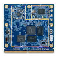
Fanless and low-power Edge AI platform with MediaTek Genio 1200 Octa-Core processor
Brand: VIA Technologies
|
Category: Computer Hardware
|
Size: 2 MB
Table of Contents
Advertisement
VIA Technologies SOM-7000 Quick Start Manual (19 pages)
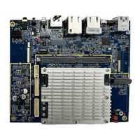
Starter Kit
Brand: VIA Technologies
|
Category: Controller
|
Size: 1 MB
Table of Contents

VIA Technologies SOM-7000 Quick Start Manual (19 pages)
Brand: VIA Technologies
|
Category: Motherboard
|
Size: 1 MB
Table of Contents
Advertisement