
Related Manuals for VIA Technologies SOM-7000


Summary of Contents for VIA Technologies SOM-7000
- Page 1 QUICK START GUIDE VIA SOM-7000 Starter Kit Fanless low-power Edge AI platform with Octa-Core MediaTek Genio 1200 processor 1.00-26092023...
- Page 2 VIA Technologies, Inc. reserves the right the make changes to the products described in this manual at any time without prior notice.
- Page 3 VIA SOM-7000 Starter Kit Quick Start Guide Safety Precautions • Always read the safety instructions carefully. • Keep this document for future reference. • All cautions and warnings on the equipment should be noted. • Keep this equipment away from humidity.
- Page 4 Octa-Core SoC, 16GB eMMC, 4GB LPDDR4 SDRAM, CSI, audio 2.2GHz/2.0GHz (headphone out and MIC-in), Wi-Fi 6+ Bluetooth 5.2, 3 Wi-Fi/ Bluetooth antenna I-PEX connectors VIA SOM-7000 starter kit with VIA SOM-7000 module, VIA STK-SOM700-00A0 SOMDB7 reference carrier board and accessory kit Optional Accessories...
-
Page 5: Table Of Contents
VIA SOM-7000 Starter Kit Quick Start Guide Table of Contents Overview ................................ 1 Hardware Installation ............................. 1 Installing the Audio Cable ........................2 Connecting the Debug Console Cable ....................2 Power Cable ............................3 Appendix A Recommended Mating/Unmating Jig ..................... 4 Jig Dimensions ............................ - Page 6 VIA SOM-7000 Starter Kit Quick Start Guide List of Figures Figure 01: Audio cable ............................1 Figure 02: Debug console cable ..........................1 Figure 03: Power cable ............................1 Figure 04: Connecting the audio cable between the module and the carrier board ..........2 Figure 05: Connecting the debug console cable between the VIA SOMDB7 carrier board and a developer PC ...
-
Page 7: Overview
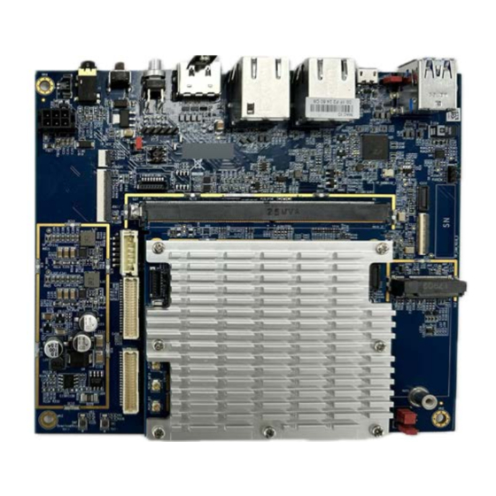
1. Overview This guide introduces and describes how to install the standard and optional accessories available for the VIA SOM-7000 starter kit, which provides a base package for testing and evaluating the VIA SOM-7000 module with the VIA SOMDB7 carrier board. -
Page 8: Installing The Audio Cable
Figure 04: Connecting the audio cable between the module and the carrier board 2.2 Connecting the Debug Console Cable Follow the steps below to connect the debug console cable between the VIA SOM-7000 starter kit and a developer PC: Step 1 Connect the white connector of the debug console cable to the debug console connector labeled 'J14' on the bottom layer of the VIA SOMDB7 carrier board. -
Page 9: Power Cable
Connect a 12V power adapter to the opposite DC-in jack end of the power cable. Note: A power adapter is not provided in the VIA SOM-7000 starter kit. A 12V 3A power adapter is bundled in the developer pack described in Appendix section B.1. -
Page 10: Appendix A Recommended Mating/Unmating Jig
VIA SOM-7000 Starter Kit Quick Start Guide Appendix A Recommended Mating/ Unmating Jig A.1 Jig Dimensions Figure 07: Mating/Unmating jig dimensions A.2 Mating Method of Plug Connector Using the jig, align the plug connector with the micro-miniature RF antenna connector (I-PEX). Then push down gently until the plug connector is fully connected. -
Page 11: Appendix B Optional Accessories
Caution: Ensure that the VIA SOM-7000 starter kit is is turned off before installing or uninstalling an optional accessory. B.1 Development Pack An optional development pack is available to test and evaluate the camera, Wi-Fi and Bluetooth networking, and power supply interfaces of the VIA SOM-7000 module and VIA SOMDB7 carrier board. -
Page 12: Figure 10: Lift The Lock Of The Mipi Csi Connector 'Csi2
VIA SOM-7000 Starter Kit Quick Start Guide Step 1 Locate the 2-lane MIPI CSI connector labeled 'CSI2' on the top layer of the VIA SOMDB7 carrier board, and gently lift its lock. Figure 10: Lift the lock of the MIPI CSI connector 'CSI2'... -
Page 13: Connecting The Bluetooth And Wi-Fi Antennas
VIA SOM-7000 Starter Kit Quick Start Guide B.1.2 Connecting the Bluetooth and Wi-Fi Antennas Follow the steps below to connect the Wi-Fi/Bluetooth antennas to the VIA SOM-7000 starter kit: Step 1 Connect a Wi-Fi/Bluetooth antenna to the Bluetooth antenna connector labeled 'WCON1 BT' on the VIA SOM- 7000 module. -
Page 14: Connecting The Power Adapter
VIA SOM-7000 Starter Kit Quick Start Guide B.1.3 Connecting the Power Adapter Follow the steps below to connect the 12V 3A power adapter to the VIA SOM-7000 starter kit: Step 1 Connect the power cable (provided in the starter kit) to the DC-in power connector labeled 'J7' on the top layer... -
Page 15: Installing The 10.1" Mipi Lcd & Touch Panel Display
VIA SOM-7000 Starter Kit Quick Start Guide B.2 Installing the 10.1" MIPI LCD & Touch Panel Display An optional 10.1" 1920x1200 MIPI LCD and touch panel display accessory is available for testing the MIPI DSI output from the VIA SOM-7000 starter kit. -
Page 16: Figure 17: Insert Lcd Touch Panel Display's Fpc Cable And Push Down The 'Jtouch1' Connector's Lock
VIA SOM-7000 Starter Kit Quick Start Guide Step 2 Insert the LCD and touch panel display's 8-pin FPC cable into the 'JTOUCH1' connector with the pins facing up, and gently push down the connector's lock. Note: The touch panel connector is of the top contact type... -
Page 17: Installing The 4G Lte M.2 Wireless Module Kit
VIA SOM-7000 Starter Kit Quick Start Guide B.3 Installing the 4G LTE M.2 Wireless Module Kit The optional 4G LTE wireless module accessory kit includes a 4G LTE M.2 module with antenna and screw pack to provide cellular connectivity (SIM card not provided). -
Page 18: Installing The Sim Card
VIA SOM-7000 Starter Kit Quick Start Guide Step 3 Connect the 4G LTE antenna to the "M" (MAIN) and "D" (DIV) I-PEX connectors on the 4G LTE module. Antenna connectors on 4G LTE module Figure 21: Connecting the antenna on the 4G LTE module... - Page 19 Taiwan Headquarters Japan China 1F, 531 Zhong-zheng Road, 940 Mission Court 3-15-7 Ebisu MT Bldg. 6F, Tsinghua Science Park Bldg. 7 Xindian Dist., New Taipei City 231 Fremont, CA 94539, Higashi, Shibuya-ku No. 1 Zongguancun East Road, Taiwan Tokyo 150-0011 Haidian Dist., Beijing, 100084 Japan China...
Need help?
Do you have a question about the SOM-7000 and is the answer not in the manual?
Questions and answers