Sign In
Upload
Manuals
Brands
VIA Technologies Manuals
Motherboard
SOM-5000
VIA Technologies SOM-5000 Manuals
Manuals and User Guides for VIA Technologies SOM-5000. We have
4
VIA Technologies SOM-5000 manuals available for free PDF download: User Manual, Quick Start Manual
VIA Technologies SOM-5000 User Manual (53 pages)
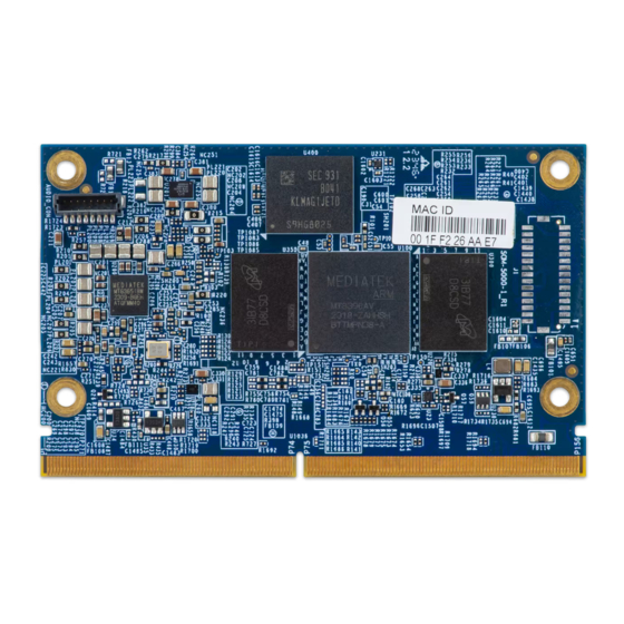
Fanless and low-power Edge AI platform with MediaTek Genio 700 Octa-Core processor
Brand:
VIA Technologies
| Category:
Computer Hardware
| Size: 2 MB
Table of Contents
Table of Contents
5
Product Overview
10
Key Features
10
Product Specifications
10
Layout Diagram
12
Figure 01: VIA SOM-5000 Module Top I/O
12
Product Dimensions
13
Figure 02: Dimensions of the VIA SOM-5000 Module (Top I/O)
13
Onboard I/O Connectors
14
Audio-Out Connector
14
Figure 03: Audio-Out Connector 'AUDIO_CON
14
Table 01: Audio-Out Connector 'AUDIO_CON' Pinouts
14
Hardware Installation
15
Installing the VIA SOM-5000 Module on the Carrier Board
15
Figure 04: Inserting the VIA SOM-5000 Module into the VIA SOMDB7 Carrier Board
15
Figure 05: Securing the VIA SOM-5000 Module on the VIA SOMDB7 Carrier Board
15
Figure 06: Secured VIA SOM-5000 Module on the VIA SOMDB7 Carrier Board
16
Software and Technical Support
17
Android/Yocto/Debian Support
17
Technical Support and Assistance
17
Appendix Avia SOMDB7 Carrier Board Reference
18
SOMDB7 Specifications
18
SOMDB7 Layout Diagram
19
Figure 07: VIA SOMDB7 Carrier Board Top I/O
19
Figure 08: VIA SOMDB7 Carrier Board Bottom I/O
20
Figure 09: VIA SOMDB7 Carrier Board Front Coastline I/O
20
Figure 10: VIA SOMDB7 Carrier Board Back Coastline I/O
20
SOMDB7 Dimensions
21
Figure 11: Dimensions of the VIA SOMDB7 Carrier Board (Top I/O)
21
Figure 12: External I/O Dimensions of the VIA SOMDB7 Carrier Board (Front Coastline I/O)
21
SOMDB7 Height Distribution
22
Figure 13: External I/O Dimensions of the VIA SOMDB7 Carrier Board (Back Coastline I/O)
22
Figure 14: Height Distribution of the VIA SOMDB7 Carrier Board (Top I/O)
22
SOMDB7 Coastline I/O Pin Descriptions and Functionality
23
Microsd Slot
23
Figure 15: Height Distribution of the VIA SOMDB7 Carrier Board (Bottom I/O)
23
Figure 16: Microsd Card Slot Diagram
23
Table 02: Microsd Card Slot Pinouts
23
USB 3.1 Ports
24
Micro USB 2.0 Port
24
Figure 17: USB 3.1 Diagram
24
Figure 18: Micro USB 2.0 Port Diagram
24
Table 03: USB 3.1 Pinouts
24
Table 04: Micro USB 2.0 Port Pinouts
24
Gigabit LAN Ports
25
HDMI® Port
25
Figure 19: Gigabit LAN Port Diagram
25
Figure 20: HDMI Port Diagram
25
Table 06: Gigabit LAN Port LED Color Definition
25
Table 05: Gigabit LAN Port Pinouts
25
Table 07: HDMI Port Pinouts
25
Power Button
26
Reset Button
26
Headphone Jack
26
Figure 21: Power Button Diagram
26
Figure 22: Reset Button Diagram
26
Figure 23: Headphone Jack Diagram
26
Table 08: Power Button Behavior Description
26
SOMDB7 Onboard I/O
27
MXM 3.0 Connector
27
Figure 24: MXM 3.0 Connector 'U37
27
Table 09: MXM 3.0 Connector 'U37' Pinouts
30
Audio-In Connector
31
Figure 25: Audio-In Connector 'AUDIO_CON
31
Table 10: Audio-In Connector 'AUDIO_CON' Pinouts
31
LVDS Connectors
32
Figure 26: LVDS Connectors 'LVDS1' and 'LVDS2
32
Table 11: 'LVDS1' Connector Pinouts
32
LVDS Backlight Connector
33
Figure 27: LVDS Backlight Connector 'J6
33
Table 12: 'LVDS2' Connector Pinouts
33
Table 13: LVDS Backlight Connector 'J6' Pinouts
33
4-Lane MIPI DSI Connector
34
Figure 28: MIPI DSI Connector 'JDSI1
34
Table 14: MIPI DSI Connector 'JDSI1' Pinouts
34
4-Lane MIPI CSI Connector
35
Figure 29: MIPI CSI Connector 'CSI1
35
Table 15: MIPI CSI Connector 'CSI1' Pinouts
35
2-Lane MIPI CSI Connector
36
Figure 30: MIPI CSI Connector 'CSI2
36
Table 16: MIPI CSI Connector 'CSI2' Pinouts
36
Touchscreen Panel Connector
37
Figure 31: Touchscreen Panel Connector 'JTOUCH1
37
Table 17: Touchscreen Panel Connector 'JTOUCH1' Pinouts
37
Volume Buttons
38
Figure 32: Volume Buttons 'SW1' and 'SW2
38
DC-In Power Connector
39
Figure 33: DC-In Power Connector 'J7
39
Table 18: DC-In Power Connector 'J7' Pinouts
39
GPIO/ADC Expansion Header
40
Figure 34: GPIO/ADC Header 'JGPIO
40
Table 19: GPIO/ADC Header 'JGPIO' Pinouts
40
RTC Battery Connector
41
Figure 35: RTC Battery Connector
41
Table 20: RTC Battery Connector Pinouts
41
M.2 B-Key Slot
42
Figure 36: M.2 B-Key Slot 'J2
42
Table 21: M.2 B-Key Slot 'J2' Pinouts
42
SIM Card Slot
43
Figure 37: SIM Card Slot 'SIM1
43
Table 22: SIM Card Slot 'SIM1' Pinouts
43
M.2 E-Key Slot
44
Figure 38: M.2 E-Key Slot 'J32
44
Table 23: M.2 E-Key Slot 'J32' Pinouts
44
Debug Console Connector
45
Table 24: Debug Console Connector 'J14
45
Table 25: Debug Console Connector 'J14' Pinouts
45
SOMDB7 Onboard Jumpers
46
Figure 39: Jumper Settings Example
46
Watchdog Jumper
47
Figure 40: Watchdog Jumper Diagram
47
Table 26: Watchdog Jumper Settings
47
Appendix B Recommended Mating/Unmating Jig
48
Jig Dimensions
48
Figure 41: MHF - I Mating/Unmating Jig Dimensions
48
Mating Method of Plug Connector
49
Figure 42: MHF - 4 Mating/Unmating Jig Dimensions
49
Figure 43: Mating the Plug Connector with the I-PEX Connector
49
Appendix C Optional Accessories
50
LTE M.2 Wireless Module Kit
50
Figure 44: Installing the SIM Card
50
Advertisement
VIA Technologies SOM-5000 Quick Start Manual (20 pages)
Debian 12 EVK
Brand:
VIA Technologies
| Category:
Computer Hardware
| Size: 2 MB
Table of Contents
Table of Contents
4
Introduction
5
EVK Package Contents
5
Firmware Folder Contents
5
Document Folder Contents
5
Version Information and Supported Features
6
Image Installation
7
Installing with the Genio Tool
7
Hardware Functions
12
Using the Debug Console
12
Changing the Kernel Debug Level
13
Checking the BSP Version
13
Dvfs
13
System Memory
14
Display
15
Video Playback
16
Audio Output and Recording
16
Camera
17
Wi-Fi
18
Bluetooth
19
MTK Neuropilot AI APU Hardware Acceleration
19
VIA Technologies SOM-5000 Quick Start Manual (18 pages)
Android 13.0 EVK
Brand:
VIA Technologies
| Category:
Motherboard
| Size: 2 MB
Table of Contents
Table of Contents
4
1 Introduction
5
EVK Package Contents
5
Firmware Folder Contents
5
Document Folder Contents
5
Tool Folder Contents
5
Version Information and Supported Features
6
2 Image Installation
7
Installing with the Genio Tool
7
3 Hardware Functions
13
Using the Debug Console
13
Changing the Kernel Debug Level
14
Checking the BSP Version
14
Dvfs
14
Display
15
Camera
15
MTK Neuropilot AI APU Hardware Acceleration
16
Advertisement
VIA Technologies SOM-5000 Quick Start Manual (11 pages)
Evaluation Kit
Brand:
VIA Technologies
| Category:
Motherboard
| Size: 1 MB
Table of Contents
Table of Contents
5
1 Overview
7
2 Evaluation Kit Assembly
7
Connecting the LCD Touch Panel
7
Figure 01: Connecting the 8-Pin FPC Cable of the Touch Panel to 'JTOUCH1
7
Figure 02: Connecting the 34-Pin FPC Cable of the LCD Display to 'JDSI1
7
Installing the Wi-Fi Wireless Module
8
Figure 03: Installing and Securing the Wi-Fi Module
8
Connecting the Camera Module
9
Figure 04: Lift the Lock of the MIPI CSI Connector 'CSI2
9
Figure 05: Insert Camera Module's FPC Cable and Push down the 'CSI2' Connector's Lock
9
Connecting the Debug Cable
10
Connecting the Power Adapter
10
Figure 06: Connecting the Debug Cable between the VIA SOMDB7 Carrier Board and a Developer PC
10
Figure 07: Connecting the Power Adapter
10
Advertisement
Related Products
VIA Technologies SOM-7000-STK Yocto 4.0.10 EVK
VIA Technologies EPIA SP 13000
VIA Technologies EPIA SP 8000E
VIA Technologies STK-VT6093-00A1
VIA Technologies STK-VT6093-01A1
VIA Technologies SOM-6X80
VIA Technologies SOM-6X50
VIA Technologies SOM-9X35
VIA Technologies SOM-9X50-STK
VIA Technologies SOM-9X35-STK
VIA Technologies Categories
Motherboard
Computer Hardware
Desktop
Control Unit
Industrial PC
More VIA Technologies Manuals
Login
Sign In
OR
Sign in with Facebook
Sign in with Google
Upload manual
Upload from disk
Upload from URL