
Related Manuals for VIA Technologies Mobile360 M820


Summary of Contents for VIA Technologies Mobile360 M820
- Page 1 USER MANUAL VIA Mobile360 M820 Fanless ultra-compact in-vehicle safety system with flexible ADAS, SVS, and DMS integration options 1.01-28042021...
- Page 2 VIA Technologies, Inc. reserves the right the make changes to the products described in this manual at any time without prior notice.
- Page 3 Battery Recycling and Disposal • Only use the appropriate battery specified for this product. • Do not re-use, recharge, or reheat an old battery. • Do not attempt to force open the battery. • Do not discard used batteries with regular trash. •...
- Page 4 VIA Mobile360 M820 User Manual Box Contents • VIA Moblie360 M820 system • Phoenix plug to DC jack • COM cable (for debugging) • GPS antenna • 2 x Wi-Fi/BT antennas Ordering Information Part Number Description M360-820-1Q20A1 Fanless mobile system with 2.054GHz Qualcomm® APQ8096A Embedded Processor, 4GB LPDDR4 SDRAM, HDMI, 2 USB 3.0, Micro USB 2.0 (debugging),...
- Page 5 VIA Mobile360 M820 User Manual Mounting Options Part Number Description M360-SBKT-00A1 Mounting bracket, 337.2mm x 185mm x 62mm...
-
Page 6: Table Of Contents
Installing the FOV Cameras and FAKRA Cables ................... 18 Unplugging the FAKRA Cable ......................19 Connecting the VIA Mobile360 M820 to the Vehicle's Ignition (IGN) ..........20 Installing the Phoenix Plug to DC Jack ....................21 Software and Technical Support ........................22 Yocto Support ............................. - Page 7 VIA Mobile360 M820 User Manual Table of Contents Appendix A Installing Wireless Accessories ..................... 23 Installing the Mobile Broadband MiniPCIe Module ................23 Appendix B Installing Automotive-Grade Cameras to the Camera Brackets ............ 26 Installing the FOV-190 Automotive-Grade Camera to the Camera Bracket ........26 Installing the FOV-35 Automotive-Grade Camera to the Camera Bracket ..........
- Page 8 Figure 01: Front panel I/O layout ......................... 4 Figure 02: Back panel I/O layout .......................... 5 Figure 03: Dimensions of the VIA Mobile360 M820 (front view) ................. 5 Figure 04: Dimensions of the VIA Mobile360 M820 (side view) ................5 Figure 05: Dimensions of the VIA Mobile360 M820 (bottom view) ..............
- Page 9 Figure 62: Adjusting the DMS camera angle ...................... 38 Figure 63: Connecting the USB power adapter cable ..................39 Figure 64: Connecting the USB cable to the VIA Mobile360 M820 ..............39 Figure 65: Mounting bracket parts ........................40 Figure 66: Installing the VIA Mobile360 M820 onto the top casing ..............40 Figure 67: Installing the base cover ........................
- Page 10 VIA Mobile360 M820 User Manual List of Tables Table 01: HDMI port pinouts ..........................7 Table 02: USB 3.0 port pinouts ........................... 7 Table 03: Micro SD card slot pinouts ........................8 Table 04: Gigabit Ethernet port pinouts ......................8 Table 05: Gigabit Ethernet port LED color definition ..................
-
Page 11: Product Overview
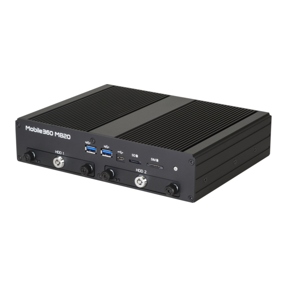
1.1.3 Optimized Integration with Multiple I/O Access With front and back panel I/O access, the VIA Mobile360 M820 can be easily configured to support a wide variety of applications with easy integration and quick setup. -
Page 12: Storage Expansion
VIA Mobile360 M820 User Manual 1.1.6 Storage Expansion The VIA Mobile360 M820 has 16GB of eMMC flash storage onboard, and features a Micro SD card slot supporting an additional 32GB, and two HDD/SSD bays for 2.5" SATA HDD/SSD. 1.1.7 Networking Support The VIA Mobile360 M820 is equipped with Wi-Fi, GPS, and an RJ-45 port that provides high-speed Gigabit Ethernet. - Page 13 VIA Mobile360 M820 User Manual Audio • TI 6PAIC3104IRHBRQ1 Audio Codec HDMI • Integrated HDMI 2.0 transmitter Expansion I/O • 1 x MiniPCIe slot (USB only) for 4G module • 1 x MiniPCIe slot (PCIe/USB) for Wi-Fi/BT module Front Panel I/O •...
-
Page 14: Layout Diagram
VIA Mobile360 M820 User Manual Mechanical Construction • Aluminum alloy top cover • Metal chassis housing Dimensions • 240mm (W) x 53mm (H) x 180mm (D) (9.45" x 2.09" x 7.09") Weight • 3.0kg (6.61lbs) Compliance • CE, FCC Notes: 1. -
Page 15: Figure 02: Back Panel I/O Layout
VIA Mobile360 M820 User Manual Figure 02: Back panel I/O layout Figure 03: Dimensions of the VIA Mobile360 M820 (front view) Figure 04: Dimensions of the VIA Mobile360 M820 (side view) -
Page 16: Figure 05: Dimensions Of The Via Mobile360 M820 (Bottom View)
VIA Mobile360 M820 User Manual Figure 05: Dimensions of the VIA Mobile360 M820 (bottom view) -
Page 17: External I/O Pin Descriptions And Functionality
2.2 USB 3.0 Ports The VIA Mobile360 M820 is equipped with two USB 3.0 ports on the front panel. Each USB 3.0 port has a maximum data transfer rate of up to 5Gbps and is backwards compatible with the USB 2.0 specification. The USB ports provides complete Plug and Play and hot swap capabilities for external devices. -
Page 18: Gigabit Ethernet Port
VIA Mobile360 M820 User Manual The VIA Mobile360 M820 is equipped with one Micro USB 2.0 port located on the front panel. The Micro USB 2.0 port supports OTG (On-The-Go) for debugging. The pinouts of the Micro USB 2.0 port are shown below. -
Page 19: Sim Card Slot
VIA Mobile360 M820 User Manual The VIA Mobile360 M820 comes with a Micro SD card slot located on the front panel with support for a maximum storage capacity of 32GB. The pinouts of the Micro SD card slot are shown below. -
Page 20: Dio Port
2.7 DIO Port The VIA Mobile360 M820 is equipped with a DIO port located on the back panel. The DIO port offers a Digital I/O communication interface to support 8-bit GPIO. The pinouts of the DIO port are show below. -
Page 21: Can Bus Port
2.10 CAN Bus Port The VIA Mobile360 M820 is equipped with a CAN bus port located on the back panel. The CAN bus port supports one CAN bus and one debug COM (TX/RX) for debugging. The CAN bus port supports protocol specification Version 2.0 B. -
Page 22: Dc-In Jack
Table 13: Power button behavior description 2.13 DC-in Jack The VIA Mobile360 M820 integrates a 4-pole Phoenix DC-in jack that carries 9~36V DC external power input. The pinouts of the 4-pole Phoenix DC-in jack are shown below. Signal DC-IN... -
Page 23: Antenna Connectors
VIA Mobile360 M820 User Manual 2.15 Antenna Connectors The VIA Mobile360 M820 is equipped with four antenna connectors located on the back panel. Two antenna connectors are used for Wi-Fi antennas, while the other two antenna connectors are used for GPS and 4G antennas. -
Page 24: Onboard I/O
This chapter provides information about the onboard I/O connector. 3.1 MiniPCIe Slot The VIA Mobile360 M820 is equipped with a miniPCIe slot for wireless networking options such as a 4G module. Then pinouts of the miniPCIe slot are shown below. -
Page 25: Hardware Installation
VIA Mobile360 M820 User Manual 4. Hardware Installation This chapter provides information about the hardware installation procedures. It is recommended to use a grounded wrist strap before handling computer components. Electrostatic discharge (ESD) can damage some components. 4.1 Installing the 2.5" SATA HDD/SSD Step 1 Insert the key and turn it in a counter clockwise direction to unlock the SATA HDD/SSD bay. -
Page 26: Figure 25: Installing The 2.5" Sata Hdd/Ssd
VIA Mobile360 M820 User Manual Step 3 Slide in the 2.5" SATA HDD/SSD into the SATA HDD/SSD bay. Then secure it with four screws. Figure 25: Installing the 2.5" SATA HDD/SSD Step 4 Reinstall the SATA HDD/SSD bays. Figure 26: Reinstalling the SATA HDD/SSD bays... -
Page 27: Installing The Wi-Fi Antennas
VIA Mobile360 M820 User Manual 4.2 Installing the Wi-Fi Antennas Step 1 Locate the two Wi-Fi antenna connectors on the back panel of the VIA Mobile360 M820. Step 2 Install the provided two Wi-Fi antennas. Figure 27: Installing the Wi-Fi antennas 4.3 Installing the GPS Antenna... -
Page 28: Installing The Fov Cameras And Fakra Cables
Figure 29: Connecting the FOV camera to the FAKRA cable Step 2 Connect the FAKRA cable to the FAKRA connector for camera-in on the Mobile360 M820. Figure 30: Connecting the FAKRA cable to the FAKRA connector... -
Page 29: Unplugging The Fakra Cable
VIA Mobile360 M820 User Manual 4.5 Unplugging the FAKRA Cable Step 1 Firmly press and hold the locking clip on the FAKRA cable's connector. Step 2 Then pull the FAKRA cable's connector to unplug it. Figure 31: Unplugging the FAKRA cable... -
Page 30: Connecting The Via Mobile360 M820 To The Vehicle's Ignition (Ign)
Connect a wire on the pin no. 8 on DIO port. Then connect the other end of the wire into the Ignition (IGN) signal of the vehicle. For details where to find the IGN on your vehicle, please refer to your car manufacturer. Figure 33: VIA Mobile360 M820 and IGN connection method diagram... -
Page 31: Installing The Phoenix Plug To Dc Jack
Figure 34: Connecting the battery cables onto the Phoenix plug to DC jack Step 2 Connect the Phoenix plug to DC jack into the DC-in jack on the VIA Mobile360 M820, and then secure it with its two screws. Figure 35: Connecting the Phoenix plug to DC jack... -
Page 32: Software And Technical Support
VIA Mobile360 M820 User Manual 5. Software and Technical Support 5.1 Yocto Support The VIA Mobile360 M820 features a complete software evaluation image featuring the Yocto 2.3 operating system. 5.2 Technical Support and Assistance • For technical support and additional assistance, always contact your local sales representative or board distributor, or go to https://www.viatech.com/en/support/technical-support/... -
Page 33: Appendix A Installing Wireless Accessories
VIA Mobile360 M820 User Manual Appendix A Installing Wireless Accessories This chapter provides information on how to install the mobile broadband miniPCIe module in the VIA Mobile360 M820. A.1 Installing the Mobile Broadband MiniPCIe Module Step 1 First, remove the two SATA HDD bays. Refer to steps 1 and 2 of section 44.1 for complete instructions. -
Page 34: Figure 37: Removing The Bottom Plate Cover
VIA Mobile360 M820 User Manual Step 3 Remove the bottom plate cover. Figure 37: Removing the bottom plate cover Step 4 Align the notch on the mobile broadband module (4G module) with the counterpart on the miniPCIe slot, then insert the module at a 30° angle. Push down the module until the screw holes align with the mounting hole on the standoff and then secure the module with a two screws. -
Page 35: Figure 39: Connecting The 4G Antenna Cable To The Micro-Rf Connector On The Module
VIA Mobile360 M820 User Manual Step 5 Connect the 4G antenna cable to the micro-RF connector labeled "MAIN" on the mobile broadband module. Then, reinstall the bottom plate cover. Figure 39: Connecting the 4G antenna cable to the micro-RF connector on the module Step 6 Install the 4G antenna on the 4G antenna connector. -
Page 36: Appendix B Installing Automotive-Grade Cameras To The Camera Brackets
VIA Mobile360 M820 User Manual Appendix B Installing Automotive-Grade Cameras to the Camera Brackets This chapter provides information on how to install the FOV-190 and FOV-35 automotive-grade cameras to the camera bracket for SVS/DMS/BSD/FCW. B.1 Installing the FOV-190 Automotive-Grade Camera... -
Page 37: Figure 43: Installing The Fov-190 Camera On The Camera Bracket
VIA Mobile360 M820 User Manual Step 3 Prepare your FOV-190 camera. Position the camera with the text label facing upward. Install the FOV-190 camera on the internal bracket, and then secure it with the two screws (M3x8) provided. Figure 43: Installing the FOV-190 camera on the camera bracket Step 4 Remove the protective cover of the double-sided adhesive tape. -
Page 38: Figure 45: Installing The Camera Bracket With Fov-190 Camera On Your Vehicle
VIA Mobile360 M820 User Manual Step 5 Install the camera bracket on the appropriate location of your vehicle. Figure 45: Installing the camera bracket with FOV-190 camera on your vehicle Caution: Once the camera bracket has been installed, it cannot be removed. Forcibly removing it could damage the double- sided adhesive tape. -
Page 39: Installing The Fov-35 Automotive-Grade Camera To The Camera Bracket
VIA Mobile360 M820 User Manual B.2 Installing the FOV-35 Automotive-Grade Camera to the Camera Bracket Step 1 Attach the internal bracket to the external bracket, and then secure it with the four screws (M3x6) provided. Figure 47: Attaching the internal bracket to the external bracket Step 2 Install the double-sided adhesive tape on the external bracket as shown in the figure below. -
Page 40: Figure 49: Preparing The Fov-35 Camera
VIA Mobile360 M820 User Manual Step 3 Prepare your FOV-35 camera. Position the camera with the text label facing downward before installing it on the internal bracket. Figure 49: Preparing the FOV-35 camera Step 4 Install the FOV-35 camera on the internal bracket, and then secure it with the two screws (M3x8) provided. -
Page 41: Figure 51: Removing The Double-Sided Adhesive Tape Protective Cover
VIA Mobile360 M820 User Manual Step 5 Remove the protective cover of the double-sided adhesive tape. Figure 51: Removing the double-sided adhesive tape protective cover... -
Page 42: Figure 52: Installing The Camera Bracket With Fov-35 Camera On Your Vehicle
VIA Mobile360 M820 User Manual Step 6 Install the camera bracket on the appropriate location of your vehicle. Figure 52: Installing the camera bracket with FOV-35 camera on your vehicle Caution: Once the camera bracket has been installed, it cannot be removed. Forcibly removing it could damage the double-... -
Page 43: Installing The Front Adas Automotive-Grade Camera
The Front ADAS automotive-grade camera comes preinstalled in a housing intended to be placed in the center of the vehicles windshield, below the rear view mirror. The housing also includes a speaker to playback the audio alerts from the VIA Mobile360 M820 system as well as a microphone which can be used to receive 2-way calls. -
Page 44: Figure 54: Removing The Protective Lens Cover
VIA Mobile360 M820 User Manual Step 2 Remove the protective lens cover on the front ADAS automotive-grade camera. Figure 54: Removing the protective lens cover Step 3 Remove the double-sided adhesive tape protective cover. Ensure the camera is positioned with arrow pointing towards the roof of the vehicle and the bottom of the triangle is parallel with the ground. -
Page 45: Figure 56: Adjusting The Front Adas Camera Angle
VIA Mobile360 M820 User Manual Step 4 To adjust the angle of the camera, remove the cover located on the right-hand side of the camera housing. Loosen two (M3x6) screws then insert a screwdriver in the outer screw to rotate the camera to the correct angle. -
Page 46: Figure 58: Connecting The 2-Pole Power Connector For The Front Adas Camera
Finally, insert the MIC (green)/GND (yellow)/HP (orange) wires to ports no. 1, 3, and 5 of the HP/MIC port on the rear I/O panel of the VIA Mobile360 M820 system. Figure 59: Connecting the HP/MIC/GND wires for the Front ADAS camera... -
Page 47: Installing The Dms Automotive-Grade Camera
VIA Mobile360 M820 User Manual B.4 Installing the DMS Automotive-Grade Camera The DMS automotive-grade camera comes preinstalled in a housing which includes a light sensor and IR LEDs for low light conditions. Following the steps below to install the DMS camera:... -
Page 48: Figure 61: Installing The Dms Camera In Your Vehicle
VIA Mobile360 M820 User Manual Figure 61: Installing the DMS camera in your vehicle Step 3 To adjust the angle of the camera, loosen the hex screw located on the right-hand side of the camera chassis with a 2.5mm Allen key. Once the camera angle has been positioned, tighten the hex screw to secure the camera. -
Page 49: Figure 63: Connecting The Usb Power Adapter Cable
FAKRA cable to the camera and system. Step 5 Connect the USB cable to either USB port located on the front I/O panel of the VIA Mobile360 M820 system. Figure 64: Connecting the USB cable to the VIA Mobile360 M820... -
Page 50: Appendix C Installing Mounting Bracket
Figure 65: Mounting bracket parts Step 1 Flip over the VIA Mobile360 M820. Install it onto the top casing of the bracket as shown in the figure below. Figure 66: Installing the VIA Mobile360 M820 onto the top casing... -
Page 51: Figure 67: Installing The Base Cover
VIA Mobile360 M820 User Manual Step 2 Flip over the base cover. Align the four screws on the base cover with the screw holes on the top casing, and then gently install the base cover. Figure 67: Installing the base cover Step 3 Secure the top casing and base cover together with the four M6 nuts as shown in the figure below. -
Page 52: Figure 69: Mounting The Via Mobile360 M820
VIA Mobile360 M820 User Manual Step 4 Find a suitable surface to mount the VIA Mobile360 M820. Drill four holes and make sure the distance between the holes are perfectly matched with the mounting bracket's holes. Step 5 Install the VIA Mobile360 M820 and secure it with M8 four screws. - Page 53 Taiwan Headquarters Japan China 1F, 531 Zhong-zheng Road, 940 Mission Court 3-15-7 Ebisu MT Bldg. 6F, Tsinghua Science Park Bldg. 7 Xindian Dist., New Taipei City 231 Fremont, CA 94539, Higashi, Shibuya-ku No. 1 Zongguancun East Road, Taiwan Tokyo 150-0011 Haidian Dist., Beijing, 100084 Japan China...
Need help?
Do you have a question about the Mobile360 M820 and is the answer not in the manual?
Questions and answers