Table of Contents
Advertisement
Quick Links
Advertisement
Table of Contents

Related Manuals for VIA Technologies Mobile360 M500

Summary of Contents for VIA Technologies Mobile360 M500
- Page 1 INSTALLATION GUIDE VIA Mobile360 Forklift Safety System 1.00-12072021...
- Page 2 OTHERWISE MADE AVAILABLE TO YOU THROUGH VIA, INCLUDING, BUT NOT LIMITED TO DIRECT, INDIRECT, INCIDENTAL, PUNITIVE, AND CONSEQUENTIAL DAMAGES, UNLESS OTHERWISE SPECIFIED IN WRITING. VIA Technologies, Inc. reserves the right the make changes to the products described in this manual at any time without prior notice. Regulatory Compliance FCC-A Radio Frequency Interference Statement This equipment has been tested and found to comply with the limits for a class A digital device, pursuant to part 15 of the FCC rules.
- Page 3 VIA Mobile360 Forklift Safety System Installation Guide Important Safety Instructions Before installing and using this product, please carefully read all the safety instructions and warnings in this user manual. Installing this product means that you have fully understood, confirmed and agreed to operate this product in accordance with the safety instructions and warnings stated in this manual.
- Page 4 VIA Mobile360 Forklift Safety System Installation Guide • It may not be possible to install this product on every type or model of forklift. Before purchasing this product, please confirm with the VIA whether this product is suitable for the type or model of the forklift you intend to install it on.
- Page 5 VIA Mobile360 Forklift Safety System Installation Guide Warranty Process During the warranty period, if this product breaks down and needs to be repaired, please follow the process below: 1. If you purchased this product from a distributor, please contact them. 2.
- Page 6 VIA Mobile360 Forklift Safety System Installation Guide Revision History Version Date Remarks 1.00 07/12/2021 Initial Release...
-
Page 7: Table Of Contents
Securing the Waterproof Cover ..................... 5 2.1.3 Attaching the I/O covers ........................ 5 2.1.4 Attaching the Vibration Dampening Strips ..................6 VIA Mobile360 M500 System Installation ..................... 7 Camera Installation ..........................8 2.3.1 Front and Rear Camera Installation ....................8 2.3.2 Driver Camera Installation ...................... - Page 8 VIA Mobile360 Forklift Safety System Installation Guide List of Figures Figure 01: Front panel I/O layout ......................... 2 Figure 02: Rear panel I/O layout .......................... 2 Figure 03: Front view system dimensions ......................2 Figure 04: Side view system dimensions ......................3 Figure 05: Bottom view system dimensions - removable panel ................
- Page 9 VIA Mobile360 Forklift Safety System Installation Guide List of Tables Table 01: MicroSD card recording times ......................4 Table 02: Driver camera installation parameters ....................10 Table 03: System LED status ..........................18 Table 04: People detection audio alerts ......................20 Table 05: Driver audio alerts ..........................
-
Page 10: Product Overview
1.1 Packing Contents • 1 x VIA Mobile360 M500 system • 2 x Vibration dampening strips •... -
Page 11: System Layout
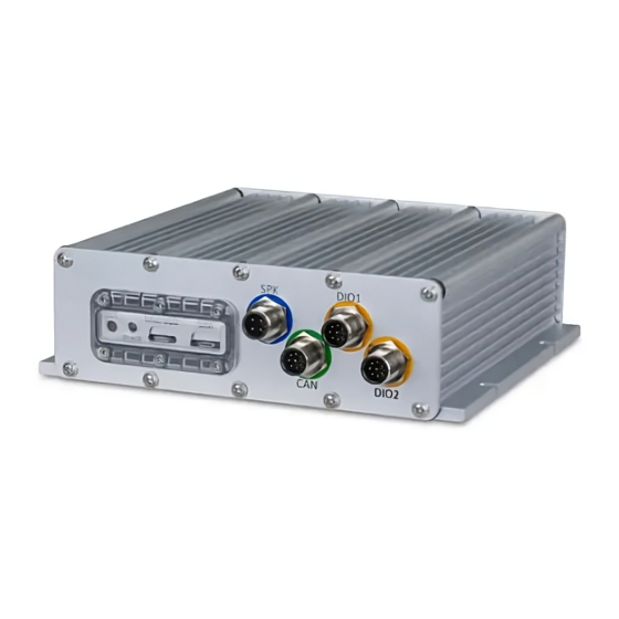
VIA Mobile360 Forklift Safety System Installation Guide 1.2 System Layout Reset Button Speaker DIO 1 MicroSD Card Slot Micro SIM Card Slot Power LED CAN/COM DIO 2 Figure 01: Front panel I/O layout CVBS Connector Rear DMOD Camera Driver Camera Front DMOD Camera Power/ACC/GND Antenna Connectors... -
Page 12: Figure 04: Side View System Dimensions
VIA Mobile360 Forklift Safety System Installation Guide 194.6mm 167mm Figure 04: Side view system dimensions 167mm 194.6mm Removable bottom panel for 4G module 178mm Figure 05: Bottom view system dimensions - removable panel... -
Page 13: Installation
I/O covers for unused ports as well as to secure the vibration dampening strips to the bottom of the system. 2.1.1 Inserting a MicroSD Card The VIA Mobile360 M500 system requires a MicroSD card to be installed in order to record video in real time. A 32GB MicroSD card is provided in the system package. Note: Failure to install a MicroSD card will not affect the operation of the system, but video will not be saved. -
Page 14: Securing The Waterproof Cover
To cover the unused ports, follow the instructions below: 1. On the front I/O panel of the VIA Mobile360 M500 system, the DIO 1, DIO 2 and the CAN/COM ports are not required for the standard setup. -
Page 15: Attaching The Vibration Dampening Strips
VIA Mobile360 Forklift Safety System Installation Guide 2. On the rear I/O panel of the VIA Mobile360 M500 system, the CVBS port (display) and the ANT-M and ANT-D (for 4G) antenna ports are not required for the standard setup. −... -
Page 16: Via Mobile360 M500 System Installation
VIA Mobile360 Forklift Safety System Installation Guide 2.2 VIA Mobile360 M500 System Installation Before Installing the VIA Mobile360 M500 system on a forklift, a suitable location should be determined based on the following criteria: • A flat surface with enough spacing to accommodate the system chassis and room for attaching the cables. -
Page 17: Camera Installation
VIA Mobile360 Forklift Safety System Installation Guide 2.3 Camera Installation The VIA Mobile360 Forklift Safety System includes three cameras to be installed on the target forklift including a driver camera for driver monitoring, and front and rear cameras for people detection. Figure 12: Camera installation locations 2.3.1 Front and Rear Camera Installation The front and rear cameras come in labeled boxes within the VIA Mobile360 Forklift Safety System package... -
Page 18: Figure 14: Front & Rear Camera Installation Locations
VIA Mobile360 Forklift Safety System Installation Guide Note: Ensure the surface has enough depth to insert the provided Molly bolts into. 2. The camera should be installed in the center of the front/rear roof bracket at a height between 1.6m ~2.7m off the ground and should have an unobstructed view (as best as possible for the front camera) looking forward. -
Page 19: Driver Camera Installation
Figure 16: Installing front & rear cameras with Molly bolts 2.3.2 Driver Camera Installation The driver camera comes in a labeled box within the VIA Mobile360 M500 Forklift Safety System and includes a color-coded cable, black, for easy identification. It comes pre-assembled with the L-shaped mounting bracket and includes a strong magnet with two M5*12mm bolts, a piece of double-sided 3M tape and two M5*25mm Molly bolts to secure the camera to the forklift. -
Page 20: Figure 18: Driver Camera Magnet Assembly
VIA Mobile360 Forklift Safety System Installation Guide Follow the steps below to install the driver camera: 1. Camera and mount assembly: There are two methods to fix the camera to the forklift: Magnet and 3M Tape - Before installing the camera to the forklift, assemble the camera and −... -
Page 21: Speaker Installation
VIA Mobile360 Forklift Safety System Installation Guide 2.4 Speaker Installation The VIA Mobile360 Forklift Safety System comes with a 2W speaker which is required to playback the audio alerts for the driver. To install the speaker, follow the steps below: 1. -
Page 22: Peripheral Cabling And Connection
It is suggested to use zip ties or tape to help secure the cables when routing. The connection between the VIA Mobile360 M500 system and the peripheral accessories may become loose due to the vibration created during operation of the forklift. It is strongly recommended to secure all M12 and... -
Page 23: Connecting Power, Acc And Ground
Connect the GPS antenna (green cable) to the "GPS" port designated in green. Figure 23: Rear I/O cable connections 2.6.1 Connecting Power, ACC and Ground The power cable for the VIA Mobile360 M500 system includes three cables to be connected to the fuse box of the target forklift as follows: •... -
Page 24: Figure 24: M12 Power Cable
Figure 25: Blade fuse holder cables Note: Before connecting power for the VIA Mobile360 M500 system, ensure the target forklift can supply the required system power ranging from 9~36V DC. Once confirmed, follow the steps below: Make sure the vehicle is turned off and follow the steps below to connect the power cable: 1. - Page 25 VIA Mobile360 Forklift Safety System Installation Guide 2. Pull out the positive power fuse from the vehicle's fuse box. 3. Select the appropriate red blade fuse holder cable. Plug in the positive power fuse that was removed from the fuse box into the free slot on the blade fuse holder cable. 4.
- Page 26 M500 power cable around the screw. Tighten the screw so the wire is firmly held. 12. Route the cable back to the VIA Mobile360 M500 system and connect the cable to the "PWR" port on the rear I/O panel designated in red.
-
Page 27: Turning System On/Off
When the system has completely shut down, the system power LED indicator will turn off. The entire shutdown process takes about 30 seconds. 2.7.1 System Reset The VIA Mobile360 M500 system includes a reset button which can be used to either perform a system power reset or a complete factory reset. •... -
Page 28: Safety Alerts & Camera Calibration
VIA Mobile360 Forklift Safety System Installation Guide 3. Safety Alerts & Camera Calibration To provide drivers with the smart situational awareness needed to safely maneuver around crowded and noisy working spaces, the VIA Mobile360 Forklift Safety System supports people detection through its front and rear cameras. -
Page 29: Front & Rear Camera Calibration
VIA Mobile360 Forklift Safety System Installation Guide The table below provides an overview of the different audio and voice alerts which can be used to notify drivers when people are detected in the warning and critical zones. See section 4.5 for how to configure the sound/voice alerts. -
Page 30: Express Mode Calibration
VIA Mobile360 Forklift Safety System Installation Guide 5. Go back to the app and the "Camera Calibration" tab will be shown. There are two options to calibrate the front and rear cameras for people detection, "Express" and "Custom" Mode. • Express Mode: Provides a simplified method for calibrating the front and rear cameras. - Page 31 VIA Mobile360 Forklift Safety System Installation Guide 5. The next step is to create the boundary lines for the warning and critical zones. Tap the "1st boundary" input box to bring up a list of boundary distances. 6. Select the desired distance for the warning/critical zone boundary. The critical zone will be the detection area less than the value selected, while the warning zone will be the detection area greater than the value selected.
-
Page 32: Figure 29: Front/Rear Camera Angle Adjustment
VIA Mobile360 Forklift Safety System Installation Guide 9. Select the desired distance for the max detection range from the list. 10. Select "Next" to proceed. 11. Next, adjust the camera so that the target crosshairs align with the edge of the black pattern printed on the box. -
Page 33: Custom Mode Calibration
VIA Mobile360 Forklift Safety System Installation Guide 12. Select "Confirm" in the top right-hand corner of the app to complete the calibration process and return to the "Camera Calibration" tab in the app. 13. The status beside the front camera will now show "Calibrated". 14. -
Page 34: Figure 30: Custom Front/Rear Camera Calibration Setup
VIA Mobile360 Forklift Safety System Installation Guide 6. If a second boundary line will be used, repeat the process to place the three markers at the desired distance of the 2nd boundary line. Figure 30: Custom front/rear camera calibration setup 7. -
Page 35: Figure 32: Front/Rear Camera Angle Adjustment
VIA Mobile360 Forklift Safety System Installation Guide 11. Next adjust the camera so that the target crosshairs align with the edge of the black pattern printed on the box. To adjust the camera, loosen the screws that connect the camera module to the camera bracket on each side. -
Page 36: Driver Camera Alerts
VIA Mobile360 Forklift Safety System Installation Guide 16. When completed, press "Confirm" in the top right-hand corner of the screen to complete the calibration process and return to the "Camera Calibration" tab in the app. 17. The status beside the front camera will now show "Calibrated". 18. -
Page 37: Driver Camera Calibration
VIA Mobile360 Forklift Safety System Installation Guide 3.2.1 Driver Camera Calibration To calibrate the driver camera, follow the steps below: 1. Open and connect the VIA Mobile360 WorkX app as described in section 3.1.1. From the "Camera Calibration" tab select "Driver Camera". 2. - Page 38 VIA Mobile360 Forklift Safety System Installation Guide 5. Select "Confirm" in the top right-hand corner of the app to complete the driver camera calibration and return to the "Camera Calibration" tab. The status beside the front camera will now show "Calibrated".
-
Page 39: Via Mobile360 Workx App
VIA Mobile360 Forklift Safety System Installation Guide 4. VIA Mobile360 WorkX App VIA Mobile360 WorkX app supports Android v5.0 and higher and iOS v12 and higher. The app can be used to calibrate the 3 cameras, adjust settings and upgrade the firmware for the VIA Mobile360 Forklift Safety system, as well as view and download videos stored on the systems MicroSD Card. -
Page 40: Upgrading System Firmware
VIA Mobile360 Forklift Safety System Installation Guide 4.2 Upgrading System Firmware When a new firmware version is available for the VIA Mobile360 Forklift Safety system, a notification will appear when first opening the VIA Mobile360 WorkX app. Press "OK" to download the new firmware to the mobile device. -
Page 41: App Menu
VIA Mobile360 Forklift Safety System Installation Guide 4.3 App Menu The menu for the VIA Mobile360 WorkX app is located along the bottom of the app interface and includes the four items described below: • Cameras - The cameras tab provides the calibration methods for each camera as well as live streams of each camera after calibration has been completed. -
Page 42: Settings
MicroSD card as exFAT. • Reset - Pressing this will perform a factory reset. The VIA Mobile360 M500 system will be restored to the factory default settings including the default Wi-Fi name and password. All camera calibration will need to be redone if pressed. -
Page 43: Album
VIA Mobile360 Forklift Safety System Installation Guide 4.6 Album From the “Album” tab, users can playback or download videos stored on the MicroSD card installed in the VIA Mobile360 Forklift Safety System. Device: When connected to a VIA Mobile360 Forklift Safety system, the "Device" tab will be accessible and show folders for each camera connected to the system. -
Page 44: Appendix A Optional Accessories
VIA Mobile360 Forklift Safety System Installation Guide Appendix A Optional Accessories A.1 7" CVBS Panel An optional 7" CVBS panel is available for the VIA Mobile360 Forklift Safety System which increases driver awareness of what is happening around their vehicle. Live video streams from the front and rear cameras are shown along with real-time visual alerts for people detection and driver monitoring alerts in the user-friendly interface. -
Page 45: Figure 34: 7" Cvbs Display Mount Assembly
VIA Mobile360 Forklift Safety System Installation Guide Figure 34: 7" CVBS display mount assembly 2. Find a suitable location to install the CVBS display mount, (along the A-pillar is recommended) and clean the surface of any dirt or debris with alcohol. 3. -
Page 46: Figure 36: 7" Cvbs Display Mount Installation With Drilling
Figure 37: 7" CVBS display installation 6. Route the cable back to the VIA Mobile360 M500 system, ensuring no part of the cable is hanging or exposed from the forklift to prevent accidental disconnection or injury. It is suggested to use zip ties or tape to help secure the cables when routing. -
Page 47: Display Interface
VIA Mobile360 Forklift Safety System Installation Guide Figure 38: 7" CVBS cable connection 8. Turn on the forklift and the display will automatically be detected and power on. A.1.3 Display Interface Once connected, the 7" CVBS display provides the driver with live views of the front and rear cameras, as well as visual alerts for people detection and driver monitoring warnings. -
Page 48: Display Buttons
VIA Mobile360 Forklift Safety System Installation Guide The default UI language is English but can be changed to other supported languages with the VIA Mobile360 WorkX app. See section 4.5 for more details. A.1.4 Display Buttons The CVBS display includes a number of indicators and buttons to adjust the display output, as shown below: Figure 40: 7"... - Page 49 Taiwan Headquarters Japan China 1F, 531 Zhong-zheng Road, 940 Mission Court 3-15-7 Ebisu MT Bldg. 6F, Tsinghua Science Park Bldg. 7 Xindian Dist., New Taipei City 231 Fremont, CA 94539, Higashi, Shibuya-ku No. 1 Zongguancun East Road, Taiwan Tokyo 150-0011 Haidian Dist., Beijing, 100084 Japan China...
Need help?
Do you have a question about the Mobile360 M500 and is the answer not in the manual?
Questions and answers