User Manuals: Vetus EC4HSM Engine Remote Control
Manuals and User Guides for Vetus EC4HSM Engine Remote Control. We have 2 Vetus EC4HSM Engine Remote Control manuals available for free PDF download: Installation & User Manual
Vetus EC4HSM Installation & User Manual (84 pages)
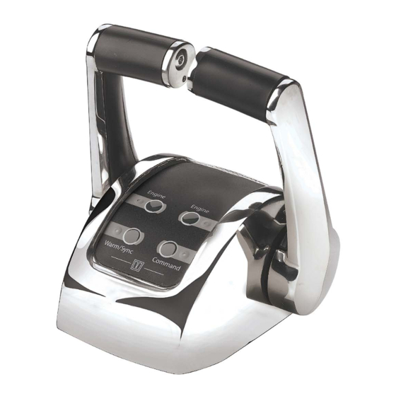
Electronic engine remote control
Brand: Vetus
|
Category: Remote Control
|
Size: 5 MB
Table of Contents
Advertisement

Vetus EC4HSM Installation & User Manual (20 pages)
Trolling & Flap option for Electronic engine remote control
Brand: Vetus
|
Category: Motorcycle Accessories
|
Size: 1 MB
Table of Contents
Advertisement