Sign In
Upload
Manuals
Brands
Vertiv Manuals
Power Supply
NetSure 5100
Vertiv NetSure 5100 Manuals
Manuals and User Guides for Vertiv NetSure 5100. We have
2
Vertiv NetSure 5100 manuals available for free PDF download: Installation Manual
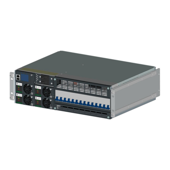
Vertiv NetSure 5100 Installation Manual (142 pages)
48 VDC Power System
Brand:
Vertiv
| Category:
Power Supply
| Size: 25.21 MB
Table of Contents
Table of Contents
3
Admonishments Used in this Document
6
Important Safety Instructions
7
Safety Admonishments Definitions
7
General Safety
7
Voltages
7
AC Input Voltages
7
DC Input Voltages
7
DC Output and Battery Voltages
8
Battery
8
Personal Protective Equipment (PPE)
9
Hazardous Voltage
9
Handling Equipment Containing Static Sensitive Components
10
Maintenance and Replacement Procedures
10
Static Warning
11
Customer Documentation Package
13
Installation Acceptance Checklist
14
Installing the System
16
General Requirements
16
Securing the Relay Rack to the Floor
16
Mounting the System in a Relay Rack or an Equipment Rack
19
Mounting the Distribution Cabinet with Module Mounting Assembly(S)
19
Installing a List 93, 94 Battery Tray
25
Installing Optional 4-Post Flush Mounting Kit for Data Cabinets, P/N
27
Changing Orientation of Load Return Busbars Located in a List
31
21, 25, or 26 Distribution Cabinet
31
Installing Optional Lug Adapter Busbar Kits
33
Installing Circuit Breakers, Fuses, and Optional Transient Voltage Surge Suppressor (TVSS) Device(S)
34
Setting Jumper and Switch Options
42
Circuit Cards with Jumpers and Switches in a List 20, 21, 25, 26, 27 Distribution Cabinet
42
Jumper Settings on the System Interface Circuit Card
45
Switch Settings on the IB2 (Controller Interface Board)
46
Board)
47
Switch Settings on the SM-DU (List 60 Hybrid Connection Cabinet)
48
Procedure
48
Making Electrical Connections
52
Important Safety Instructions
52
Wiring Considerations
52
Relay Rack / Cabinet Frame Grounding Connection
53
Connection
53
Central Office Ground Connection
53
Rectifier Nominal 120 VAC / 208 VAC / 240 VAC Input and AC Input Equipment Grounding Connections
55
Wiring Considerations
55
To 19" or 23" Rectifier AC Input / Solar Converter DC Input Panel (List 40, 45) and 23" Rectifier AC Input Panel (List 46)
55
To Individual Module Mounting Assembly(S) Equipped with Molex
59
Rectifier AC Input Line Cords
59
Connections
60
Wiring Considerations
60
To 19" or 23" Rectifier AC Input / Solar Converter DC Input Panel (List 40, 45)
60
To 23" Solar Connection Cabinet (List 61)
63
To Individual Module Mounting Assembly(S) Equipped with Molex
63
Assemblies
63
Connection Cabinet
66
External Alarm, Reference, Monitoring, and Control Connections
67
External Alarm, Reference, Monitoring, and Control Connection
67
Locations
67
System Interface Circuit Card Connections (if Required)
70
RS485 Modbus Connection (if Required)
71
IB2 (Controller Interface Board) Connections (if Required)
71
Required)
79
Optional EIB (Controller Extended Interface Board) Connections
81
Circuit Breaker Alarm and Shunt Monitoring Connections to an Optional List 60 Hybrid Connection Cabinet
85
Optional Customer Fuel Sensor Input
87
Connecting a Device or System to the NCU CAN Bus (if Required)
88
NCU Controller Ethernet Connection (if Required)
88
Control Bus Connections between Controller and Module Mounting
91
Assemblies
91
Optional Transient Voltage Surge Suppressor (TVSS) Device
93
Ground Connection
96
Load Connections
97
Load Connections to a List 20, 25 Distribution Cabinet
97
Load Connections to a List 21, 26 Distribution Cabinet
102
Load Connections to a List 27 Distribution Cabinet
109
Load Connections to an Optional GMT Fuse Block
112
Load Connections to a List KG Distribution Panel
113
Connections to an Optional List 60 Hybrid Connection Cabinet
114
Input Battery Connections
115
Input Battery Connections to List 20, 25 Distribution Cabinet
115
Input Battery Connections to List 21, 26 Distribution Cabinet
120
Input Battery Connections to List 27 Distribution Cabinet
125
Remote Distribution Unit (DU) Connections
125
List 27 Distribution Cabinet
125
Installing and Connecting Batteries in an Optional List 93 or
127
Battery Tray (if Furnished)
127
Important Safety Instructions
127
Installing Rectifier, Solar Converter, and Converter Modules
130
Initially Starting, Configuring, and Checking System Operation
134
Important Safety Instructions
134
Initial Startup Preparation
134
Initially Starting the System
134
NCU Controller Initialization
134
Application
136
Checking System Status
140
Final Steps
141
Advertisement
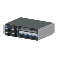
Vertiv NetSure 5100 Installation Manual (80 pages)
-48 VDC Power System
Brand:
Vertiv
| Category:
Power Supply
| Size: 7.75 MB
Table of Contents
Table of Contents
3
Admonishments Used in this Document
5
Important Safety Instructions
6
General Safety
6
Voltages
6
AC Input Voltages
6
DC Output and Battery Voltages
6
Battery
7
Personal Protective Equipment (PPE)
8
Hazardous Voltage
8
Handling Equipment Containing Static Sensitive Components
8
Maintenance and Replacement Procedures
8
Static Warning
9
Customer Documentation Package
11
Installation Acceptance Checklist
11
Installing the System
13
General Requirements
13
Securing the Relay Rack to the Floor (if Furnished)
13
Securing the System to a Relay Rack or a Cabinet Equipment Rack
15
(If Required)
15
Securing the System Vertically to a Wall with P/N 553203Kit
17
Furnished)
19
Securing the System Horizontally to a Wall with P/N 552537 or P/N
19
552535 Kit (if Furnished)
19
Installing a List 93, 94 Battery Tray
22
Installing Circuit Breakers and Fuses
25
Installing an Optional Battery Cabinet
27
Installing an Optional External IB4 Kit P/N 561929
28
Attaching the USB Drive Pouch to the System
29
Setting Jumper and Switch Options
30
Circuit Card Locations
30
Jumper Settings on the System Interface Circuit Card
31
Switch Settings on the IB2 (Controller Interface Board) (if Furnished)
33
Making Electrical Connections
35
Important Safety Instructions
35
Wiring Considerations
35
Relay Rack / Cabinet Frame Grounding Connection
35
System Shelves Frame Grounding Connection
36
Central Office Ground Connection
38
Rectifier Nominal 120 VAC / 208 VAC / 240 VAC Input and AC Input Equipment Grounding Connections
38
External Alarm, Reference, Monitoring, and Control Connections
41
Circuit Card Locations
41
RS-485 Connection (Used for Communication with SM Modules)
42
Temperature Probes
42
System Interface Circuit Card Connections (if Required)
42
IB2 (Controller Interface Board) Connections (if Furnished)
44
Connecting a Device or System to the NCU CAN Bus (if Required)
54
NCU Controller Ethernet Connection (if Required)
55
Control Bus Connections between Controller and System Shelves
57
Wiring
57
Load Distribution Wiring, Input Battery Wiring, and CO Ground Wiring
59
To List BF and NF
59
To List BC, LC, and NC
60
To List BA and NA
60
Load Distribution Wiring, Input Battery Wiring, and CO Ground Wiring
61
Load Distribution Wiring, Input Battery Wiring, and CO Ground Wiring
62
Connecting to an Optional Battery Cabinet
64
Installing and Connecting Batteries in an Optional List 93 or
64
Battery Tray (if Furnished)
64
Installing Rectifier Modules
67
Initially Starting, Configuring, and Checking System Operation
67
Initial Startup Preparation
67
Initially Starting the System
67
NCU Controller Initialization
67
Application
70
Checking System Status
79
Final Steps
79
Advertisement
Related Products
Vertiv NetSure 512NGBB
Vertiv NetSure 531 A41
Vertiv 582127000600-901
Vertiv 582127000600
Vertiv 582127000901
Vertiv 582137000
Vertiv NetSure 588820200SK001
Vertiv 582127000102
Vertiv 582127000501
Vertiv 582127000502
Vertiv Categories
UPS
Power Supply
Switch
Power distribution unit
Air Conditioner
More Vertiv Manuals
Login
Sign In
OR
Sign in with Facebook
Sign in with Google
Upload manual
Upload from disk
Upload from URL