Sign In
Upload
Manuals
Brands
Vertiv Manuals
Power Supply
NetSure 502NGFB Series
Vertiv NetSure 502NGFB Series Manuals
Manuals and User Guides for Vertiv NetSure 502NGFB Series. We have
2
Vertiv NetSure 502NGFB Series manuals available for free PDF download: Application Manual, Installation Manual
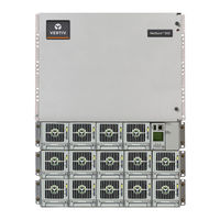
Vertiv NetSure 502NGFB Series Application Manual (129 pages)
Brand:
Vertiv
| Category:
Portable Generator
| Size: 17 MB
Table of Contents
System Overview
1
Table of Contents
5
Main Components Illustrations
9
Lists 1 - 4
9
Lists 5-8
10
Lists 10-13
11
Lists 14 - 17
11
Lists 20 - 23
13
Lists 26, 27
14
Other
15
List Descriptions
16
List Numbers
16
List 1: 19" Main Shelf
16
List 2: 19" Expansion Shelf
16
List 3: 23" Main Shelf
17
List 4: 23" Expansion Shelf
17
List 5: 19" Assembled System with One (1) Main Shelf and AC Input / Bulk DC Output Termination Panel
17
List 6: 19" Assembled System with One (1) Main Shelf, One (1) Expansion Shelf, and AC Input / Bulk DC Output Termination Panel
18
List 7: 23" Assembled System with One (1) Main Shelf and AC Input / Bulk DC Output Termination Panel
18
List 8: 23" Assembled System with One (1) Main Shelf, One (1) Expansion Shelf, and AC Input / Bulk DC Output Termination Panel
19
List 10: 19" Assembled System with One (1) Main Shelf and Space for One (1) Distribution Cabinet
20
List 11: 19" Assembled System with One (1) 19" Main Shelf, One (1) Expansion Shelf, and Space for One (1) Distribution Cabinet
20
List 12: 23" Assembled System with One (1) Main Shelf and Space for One (1) Distribution Cabinet
21
List 13: 23" Assembled System with One (1) Main Shelf, One (1) Expansion Shelf, and Space for One (1) Distribution Cabinet
21
List 14: 19" Field Expansion Shelf
22
List 15: 23" Field Expansion Shelf
22
List 16: 19" Assembled System with One (1) Main Shelf, Two (2) Expansion Shelves, and Space for One (1) Distribution Cabinet
22
List 17: 23" Assembled System with One (1) Main Shelf, Two (2) Expansion Shelves, and Space for One (1) Distribution Cabinet
23
List 20: 19" Assembled System with One (1) Main Shelf and Space for One (1) GMT Distribution Panel and One (1) Distribution Cabinet
23
List 21: 19" Assembled System with One (1) Main Shelf, One (1) Expansion Shelf, and Space for One (1) GMT Distribution Panel and One (1) Distribution Cabinet
24
List 22: 23" Assembled System with One (1) Main Shelf and Space for One (1) GMT Distribution Panel and One (1) Distribution Cabinet
25
List 23: 23" Assembled System with One (1) Main Shelf, One (1) Expansion Shelf, and Space for One (1) GMT Distribution Panel and One (1) Distribution Cabinet
25
List 26: 19" Assembled System with One (1) Main Shelf, Two (2) Expansion Shelves, and Space for One (1) GMT Distribution Panel and One (1) Distribution Cabinet
26
List 27: 23" Assembled System with One (1) Main Shelf, Two (2) Expansion Shelves, and Space for One (1) GMT Distribution Panel and One (1) Distribution Cabinet
26
List 89: Relay Rack Earthquake Anchor Kit, P/N P0987167
28
List 90: Optional Temperature Probe, 12-Ft. Total Cable Length
28
List 91: Optional Temperature Probe, 33-Ft. Total Cable Length
29
List 93: Battery Tray Assembly, Pre-Cabled, for 23" Relay Rack
29
List 94: Battery Tray Assembly, Pre-Cabled, for 19" Relay Rack
33
Distribution Cabinets
37
List AA: 23" 1-Row Distribution Cabinet with (24) Load Positions and Low Voltage Battery Disconnect (LVBD)
37
List AB: 23" 1-Row Distribution Cabinet with (24) Load Positions and Low Voltage Load Disconnect (LVLD)
38
List AC: 23" 1-Row Distribution Cabinet with (24) Load Positions and no Low Voltage Disconnect (LVD)
39
Voltage Battery Disconnect (LVBD)
40
List BB: 23" 1-Row Distribution Cabinet with (18) Load Positions, (6) Battery Disconnect Positions and Low Voltage Load Disconnect (LVLD)
41
List BC: 23" 1-Row Distribution Cabinet with (18) Load Positions, (6) Battery Disconnect Positions and no Low Voltage Disconnect (LVD)
42
List CA: 23" 1-Row Distribution Cabinet with (16) Load Positions, (8) Battery Disconnect Positions and Low Voltage Battery Disconnect (LVBD)
43
List CB: 23" 1-Row Distribution Cabinet with (16) Load Positions, (8) Battery Disconnect Positions and Low Voltage Load Disconnect (LVLD)
44
List CC: 23" 1-Row Distribution Cabinet with (16) Load Positions, (8) Battery Disconnect Positions and no Low Voltage Disconnect (LVD)
45
List FA: 19" 1-Row Distribution Cabinet with (19) Load Positions and Low Voltage Battery Disconnect (LVBD)
46
List FB: 19" 1-Row Distribution Cabinet with (19) Load Positions and Low Voltage Load Disconnect (LVLD)
47
List FC: 19" 1-Row Distribution Cabinet with (19) Load Positions and no Low Voltage Disconnect (LVD)
48
List GA: 19" 1-Row Distribution Cabinet with (14) Load Positions, (5) Battery Disconnect Positions and Low Voltage Battery Disconnect (LVBD)
49
List GB: 19" 1-Row Distribution Cabinet with (14) Load Positions, (5) Battery Disconnect Positions and Low Voltage Load Disconnect (LVLD)
50
List GC: 19" 1-Row Distribution Cabinet with (14) Load Positions, (5) Battery Disconnect Positions and no Low Voltage Disconnect (LVD)
51
List KG: 19"/23" 20-Position GMT Fuse Panel (P/N 545590)
52
List MA: 23" 2-Row Distribution Cabinet with (39) Load Positions, (9) Battery Disconnect Positions and Low Voltage Battery Disconnect (LVBD)
53
List MB: 23" 2-Row Distribution Cabinet with (39) Load Positions, (9) Battery Disconnect Positions and Low Voltage Load Disconnect (LVLD)
54
List MC: 23" 2-Row Distribution Cabinet with (39) Load Positions, (9) Battery Disconnect Positions and no Low Voltage Disconnect (LVD)
55
List MD: 23" 2-Row Distribution Cabinet with (39) Load Positions, (9) Battery Disconnect Positions, Low Voltage Load Disconnect (LVLD) and Low Voltage Battery Disconnect (LVBD)
56
List MV: 23" 2-Row Distribution Cabinet with (48) Load Positions, and no Low Voltage Disconnect (LVD)
57
List NA: 23" 2-Row Distribution Cabinet with (28) Load Positions, (20) Battery Disconnect Positions and Low Voltage Battery Disconnect (LVBD)
58
List NB: 23" 2-Row Distribution Cabinet with (28) Load Positions, (20) Battery Disconnect Positions and Low Voltage Load Disconnect (LVLD)
59
List NC: 23" 2-Row Distribution Cabinet with (28) Load Positions, (20) Battery Disconnect Positions and no Low Voltage Disconnect (LVD)
60
List ND: 23" 2-Row Distribution Cabinet with (28) Load Positions, (20) Battery Disconnect Positions, Low Voltage Load Disconnect (LVLD) and Low Voltage Battery Disconnect (LVBD)
61
List RA: 19" 2-Row Distribution Cabinet with (29) Load Positions, (9) Battery Disconnect Positions and with Low Voltage Battery Disconnect (LVBD)
62
List RB: 19" 2-Row Distribution Cabinet with (29) Load Positions, (9) Battery Disconnect Positions and Low Voltage Load Disconnect (LVLD)
63
List RC: 19" 2-Row Distribution Cabinet with (29) Load Positions, (9) Battery Disconnect Positions and no Low Voltage Disconnect (LVD)
64
List RD: 19" 2-Row Distribution Cabinet with (29) Load Positions, (9) Battery Disconnect Positions, Low Voltage Battery Disconnect (LVBD) and Low Voltage Load Disconnect (LVLD)
65
Accessory Descriptions
66
Rectifier
66
Rectifier Module, High Efficiency
66
Controller
66
NCU (Netsure Control Unit), P/N 1M830BNA
66
IB2 Interface Board Assembly, P/N MA4C5U31 / 548181
67
Optional Temperature Probes
68
Distribution Devices
69
Bullet Nose Type Circuit Breakers
69
TPS/TLS-Type Fuses
70
GMT Load Distribution Fuses
71
Bullet Nose Bypass Bus Bar, P/N 535015
71
Plug-In GMT Fuse Distribution Assembly, P/N 545333 for 1-Row Distribution Cabinet / P/N 549017 for 2-Row Distribution Cabinet
72
Special Application Lugs, Busbar Adapter Kits and Hardware Kits
72
Special Application Crimp Lugs
72
Busbar Adapter and Hardware Kits
73
Rear-Facing Return Busbars for 2-Row Distribution Cabinets
74
SM TEMP Temperature Concentrator (P/N 547490)
75
Mounting Bracket Kits (P/N 553336 and P/N 555231)
76
Mounting Bracket Kits (P/N 556342, P/N 556343, and P/N 556346)
77
Optional Wall Mounting Bracket Kits
79
Optional 19" 6RU Wall Mount Bracket Kit, P/N 552537
79
Optional 23" 6RU Wall Mount Bracket Kit, P/N 552535
79
19" Termination Panel Kit (P/N 555234)
80
19 ” Termination Panel Kit (P/N 555234)
82
Relay Racks
82
Transition Plates to Mount Relay Rack on Top of GNB Absolyte® IIP Batteries
83
AC Input Cables and Line Cords
84
AC Input Cable Assembly, P/N 535232
84
AC Input Cable Assembly, P/N 553202
84
AC Input Line Cord, P/N 540946
85
AC Input Line Cord, P/N 559301
85
AC Input Line Cord, P/N 545616
86
AC Input Line Cord, P/N 559302
86
AC Input Line Cord, P/N 545252
86
AC Cord Bracket Kits (P/N 560161 and P/N 560162)
87
Battery Cables, P/N 559124
87
Alarm Cables
87
User Replaceable Components
88
Wiring Notes
89
AC Input Connections
89
DC Output Connections
89
Battery Connections
94
C.O. Ground Connection
95
External Alarm and Monitoring Connections
95
Wiring Illustrations
96
AC Input Connections (All Lists)
96
Bulk DC Output Connections (Lists 1 - 4)
98
Bulk DC Output and C.O. Ground Connections (Lists 5 - 8)
99
DC Load, C.O. Ground and Battery Connections (1-Row Distribution Cabinets)
100
List MA-MD, NA-ND, RA-RD DC Load, C.O. Ground and Battery Connections (2-Row Distribution Cabinets)
101
List MV DC Load, C.O. Ground and Battery Connections (2-Row Distribution Cabinet)
102
External Alarm and Monitoring Wiring
103
Remote Shunt Connections (Lists 5 - 8)
104
1 System
105
1.1 Environmental Ratings
105
1.2 Compliance Information
105
Specifications
105
1.3 Standard Features
106
1.4 IB2 (Controller Interface Board) Ratings
106
2 Rectifier
106
Mechanical Specifications
107
Overall Dimensions - List 1, List 2
107
Overall Dimensions - List 3, List 4
108
Overall Dimensions - List 5, List 6
109
Overall Dimensions - List 7, List 8
110
Overall Dimensions - List 10, List 11, with Distribution
111
Overall Dimensions - System with 19" 6RU Wall Mount Kit P/N 552537 (Cont'D on Next Page)
112
Overall Dimensions - System with 19" 6RU Wall Mount Kit P/N 552537 (Cont'D from Previous Page)
113
Overall Dimensions - System with 23" 6RU Wall Mount Kit P/N 552535 (Cont'D on Next Page)
114
Overall Dimensions - System with 23" 6RU Wall Mount Kit P/N 552535 (Cont'D from Previous Page)
115
Overall Dimensions - List 14, List 15
117
Overall Dimensions - List 16 with Distribution
118
Overall Dimensions - List 17 with Distribution
119
Overall Dimensions - List 20 with Distribution
120
Overall Dimensions - List 21 with Distribution
121
Overall Dimensions - List 22 with Distribution
122
Overall Dimensions - List 23 with Distribution
123
Overall Dimensions - List 26 with Distribution
124
Overall Dimensions - List 27 with Distribution
125
Overall Dimensions - List 93 (23" Battery Tray)
126
Overall Dimensions - List 94 (19" Battery Tray)
127
Battery Manufacturer Information
128
Related Documentation
128
Revision Record
129
3 Controller
106
Advertisement
Vertiv NetSure 502NGFB Series Installation Manual (86 pages)
Brand:
Vertiv
| Category:
Power Supply
| Size: 6 MB
Table of Contents
Table of Contents
3
Admonishments Used in this Document
5
Important Safety Instructions
6
General Safety
6
Voltages
6
AC Input Voltages
6
DC Output and Battery Voltages
6
Battery
7
Personal Protective Equipment (PPE)
8
Hazardous Voltage
8
Handling Equipment Containing Static Sensitive Components
8
Maintenance and Replacement Procedures
8
Static Warning
9
Customer Documentation Package
11
Installation Acceptance Checklist
11
Installing the System
12
General Requirements
12
Securing the Relay Rack(S) to the Floor (if Furnished)
13
Securing the Power/Distribution Shelf to a Relay Rack or Cabinet
16
Securing the Power/Distribution Shelf to a Wall with a Part no
16
553203 Kit
16
Securing the System Horizontally to a Wall with P/N 552537 or P/N
18
552535 Kit (if Furnished)
18
Installing Circuit Breakers and Fuses
21
Installing an Optional Battery Cabinet
25
Making Electrical Connections
26
Important Safety Instructions
26
Wiring Considerations
26
Relay Rack Frame Grounding Connection
26
Power/Distribution Shelf Frame Grounding Connection
26
AC Input and AC Input Equipment Grounding Connections
26
External Interface Connections
30
IB2 (Controller Interface Board) Connections
30
Ethernet Connection
36
Load Connections
38
To GMT Fuse Positions (List BF and NF)
38
To GMT Fuse Positions (List BA, NA, BC, LC and NC)
40
To Bullet Nose-Type Load Distribution Circuit Breaker Positions
41
BC, LC, and NC)
41
To Bullet Nose-Type Load Distribution Circuit Breaker Positions
42
BA and NA)
42
List KG GMT Load Distribution Fuse Panel
43
CO Ground Connection
44
Battery Connections
44
To Battery Busbars
44
To Bullet Nose-Type Circuit Breaker Positions (Lists BA and NA)
44
Installing and Connecting Batteries in an Optional Battery Tray
46
Furnished)
46
Optional External Battery Disconnect Unit
49
Connecting to an Optional Battery Cabinet
53
Installing the Rectifier Modules
54
Initially Starting the System
55
Initially Starting, Configuring, and Checking System Operation When
55
E/W NCU
55
Initial Startup Preparation
55
NCU Controller Initialization
55
NCU Start Wizard
57
Verifying the Configuration File
57
Checking Basic System Settings
57
Checking System Status
58
Configuring the NCU Identification of Rectifiers and Assigning Which Input Feed Is Connected to the Rectifiers
59
NCU Alarm Relay Check
59
Final Steps
64
Initially Starting, Configuring, and Checking System Operation When
65
E/W ACU
65
Initial Startup Preparation
65
Initially Starting the System
65
ACU+ Initialization
65
Verifying the Configuration File
67
Checking Basic System Settings
67
Checking System Status
68
Configuring the ACU+ Identification of Rectifiers and Assigning Which Input Phase Is Connected to each Rectifier
68
ACU+ Alarm Relay Check
69
Final Steps
75
Initially Starting, Configuring, and Checking System Operation When
76
E/W SCU
76
Initial Startup Preparation
76
Initially Starting the System
76
SCU+ Initialization
76
Verifying the Configuration File
78
Checking System Status
78
Configuring the SCU+ Identification of Rectifier Modules
78
SCU+ Alarm Relay Check
79
Final Steps
84
Advertisement
Related Products
Vertiv NetSure 531 AC1
Vertiv 581126000
Vertiv 588250400
Vertiv 588250300
Vertiv 582127000600-901
Vertiv 582127000901
Vertiv NetSure 512NGBB
Vertiv NetSure 588820200SK002
Vertiv NetSure 588820200SK003
Vertiv NetSure 588820200SK004
Vertiv Categories
UPS
Power Supply
Switch
Power distribution unit
Air Conditioner
More Vertiv Manuals
Login
Sign In
OR
Sign in with Facebook
Sign in with Google
Upload manual
Upload from disk
Upload from URL