Sign In
Upload
Manuals
Brands
Vertiv Manuals
Control Panel
Liebert EXL S1
Vertiv Liebert EXL S1 Manuals
Manuals and User Guides for Vertiv Liebert EXL S1. We have
6
Vertiv Liebert EXL S1 manuals available for free PDF download: Installer's Manual, Operation And Maintenance Manual, User Manual, Installation Manual
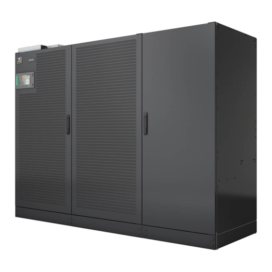
Vertiv Liebert EXL S1 Installer's Manual (243 pages)
400 kVA-1200 kVA, 60 Hz, three-phase UPS, single-module and multi-module
Brand:
Vertiv
| Category:
UPS
| Size: 39 MB
Table of Contents
Table of Contents
3
1 Important Safety Instructions
5
2 Mechanical Installation
7
Pre-Installation Planning
7
Preliminary Checks
7
Environmental Considerations
7
UPS Room
7
Storing the UPS and Batteries for Delayed Installation
9
Installation Altitude
9
Positioning
9
Moving the Cabinets
9
Clearances
10
Raised-Floor Installations
10
Floor Anchors-Optional
10
Kick Plate Installation-Standard
10
Special Considerations for 1+N Parallel Systems
10
Unpacking and Unloading the Cabinet from the Pallet
11
System Configuration
12
Power-Cable Busbars
14
Attaching Input/Output Cabinets
18
Moving Input/Output Cabinets into Position
18
3 UPS Electrical Installation
19
External Protective Devices
19
Power Cables
19
Sizing the Input Breaker that Feeds the UPS
20
Single or Dual Input Feeds
20
Automatic Transfer Switches
20
Input Power Cable Connection
20
Equipment Ground
21
DC Power Connections
22
Control Cable and Communication
23
Slots for Liebert® Intellislot™ Cards-SLOT1 and SLOT3
25
Slot for LIFE Services Products-SLOT2
25
Serial Interface for Liebert® LIFE™ Services Cards (Serial Input/Output)-XP6
25
Connector for REPO (Input and Status)-AP30-XP10
26
Customizable Output Dry Contacts-AP30/AP202 XP12
26
Customizable Input Dry Contacts-AP30/AP202 XP11
29
Connector for Parallel UPS Connection-AP30-XP71A, 71B, AP30-XP72A, 72B
31
Interface for Synchronization with External Signal-AP30-XP31
32
UPS Control Contacts with Battery Cabinet or Module Battery Disconnect
32
UPS Control Contacts with Global Maintenance Bypass
32
Vertiv | EXL S1™ Installer Guide
32
Configuring Ground Connections
33
Three-Wire Input Connections
33
Recommended Grounding Configuration, Battery Systems
35
High-Resistance Ground Systems
36
Distributed Static Switch (1+N) System Cabling Layouts
36
Top Entry Low-Voltage
37
Bottom Entry Low-Voltage
37
4 Optional Equipment
39
Options
39
Rectifier Feed Breaker (RFB)
40
Remote Back-Feed Breaker
40
Multi-Module System Options and Accessories
41
Paralleling Cable Kit
42
Multi-Bus Synch Module (MBSM)
42
5 Specifications
43
Appendices
57
Appendix A: Technical Illustrations
57
Advertisement
Vertiv Liebert EXL S1 Installation Manual (87 pages)
Large System, 3-Phase UPS Battery System
Brand:
Vertiv
| Category:
UPS
| Size: 12 MB
Table of Contents
Table of Contents
4
Important Safety Instructions
10
1 Mechanical Installation
13
Introduction
13
Preliminary Checks
13
Environmental Considerations
13
Battery Room
13
1.3.2 Storage for Delayed Installation
13
Positioning
15
Moving the Cabinets
15
Figure 1 Shipping Bolts-Top-Terminal Battery Cabinet, Standard Width
16
Figure 2 Shipping Bolts-Top-Terminal Battery Cabinet, Reduced Width
16
1.4.2 Clearances
17
1.4.3 Raised Floor Mounting
17
System Composition
17
2 Battery Installation
18
Safety
18
Layout
19
Figure 3 Top-Terminal Battery System Configurations-Liebert® EXL
19
Figure 4 Top-Terminal Battery System Configurations Attached to UPS-Liebert® EXL™ S1
20
Figure 5 Top-Terminal Battery System Configurations-Liebert® NX™ 225-600Kva
21
Figure 6 Top-Terminal Battery System Configurations-Liebert® NXL
22
Figure 7 Top-Terminal Stand-Alone Battery System Configuration-Liebert® EXL™, Liebert® EXL™ S1
23
Figure 8 Top-Terminal Battery System Configuration-Battery Cabinets Not Attached to UPS or each
23
Figure 9 Front-Terminal Battery System Configurations-Liebert® EXL
24
Figure 10 Front-Terminal Battery System Configurations Attached to UPS-Liebert® EXL™ S1
25
Figure 11 Front-Terminal Battery System Configurations-Liebert® NX
26
Figure 12 Front-Terminal Battery System Configurations-Liebert® NXL
27
Control Cable Entry
28
DC Power Connections
28
2.4.1 Connected Battery Systems
28
2.4.2 Connected or Stand-Alone Arrangement
28
Figure 13 Front-Terminal Stand-Alone Battery System Configuration-Liebert® EXL™, Liebert® EXL™ S1
28
Figure 14 Front-Terminal Battery System Configuration-Battery Cabinets Not Attached to UPS or each
28
2.4.3 DC Power Connections-Liebert® EXL™ S1
29
2.4.4 Grounding
30
Control Connections
30
Figure 15 Control Cable Layout-Liebert® UPS to Liebert® Battery Cabinet
30
2.5.1 Liebert® EXL™ and Liebert® EXL™ S1-UPS Control Contacts with Battery Cabinet
31
Figure 16 TB1154 Location-Liebert® EXL
31
Table 1 Liebert® EXL™ and Liebert® EXL™ S1 UPS Control Contacts to Battery Interface Boards
31
2.5.2 Liebert® NX™-UPS Control Contacts with Battery Cabinet
32
Figure 17 TB1154 Location, BIB Connection-Liebert® EXL™ S1
32
Figure 18 TB3 Location-225-300Kva Liebert® NX™, SMS and 1+N Multi-Module Unit with Static
33
Table 2 Liebert® NX™UPS Control Contacts to Battery Interface Boards
33
Figure 19 TB3 Location-Liebert® NX™ 400-600Kva, SMS and 1+N Multi-Module Unit with Stat- IC
34
2.5.3 Liebert® NXL™-UPS Control Contacts with Battery Cabinet
35
Figure 20 Wiring External Interface Board in Liebert® NXL™ to Battery Interface Board in Battery
35
Alber® Monitoring System-Optional
36
External Battery Room Temperature Sensor-Optional
36
Figure 21 Battery Temperature Sensor Control Connection
37
Figure 22 Outline and Terminal Details, Optional Auxiliary Temperature Sensor for Liebert® EXL
38
3 Installation Drawings
39
Installation Drawings-Top Terminal Battery Cabinets
39
Figure 23 Top-Terminal Battery Cabinet Layout
39
Figure 24 Ground Strap Location for Connected Top-Terminal Battery Cabinets
40
Figure 25 Outline Drawing, Liebert® Top-Terminal, 47" (1194Mm) Wide Battery Cabinet (1194Mm)
41
Figure 27 Outline Drawing, Liebert® Top-Terminal, 55" (1400Mm) Wide Battery Cabinet for Lieb- Ert
43
Figure 28 Main Components, Top-Terminal, 55" (1400Mm) Wide Battery Cabinet for Liebert
44
Figure 29 Terminal Details, Top-Terminal, 55" (1400Mm) Wide Battery Cabinet for Liebert® EXL™, Liebert® EXL™ S1, Liebert® NX™ 225-600Kva and Liebert® NXL
45
Battery
46
Figure 31 Liebert® EXL™ S1 625-800Kva UPS Input/Output Cabinet 1 to Top-Terminal Battery
47
Figure 32 Liebert® EXL™ S1 1000-1200Kva UPS Input/Output Cabinet 1 to Top-Terminal Battery
48
Figure 33 Liebert® EXL™ S1 625-800Kva UPS Input/Output Cabinet 2 or 3 to Top-Terminal Bat
49
Figure 34 Liebert® EXL™ S1 1000-1200Kva UPS Input/Output Cabinet 2 or 3 to Top-Terminal
50
Figure 35 Busbar Shroud for Input/Output Cabinet 2 or 3, Top-Terminal or Front-Terminal Battery
51
Ebert
51
Installation Drawings-Front Terminal Battery Cabinets
52
Figure 36 Front-Terminal Battery Cabinet Layout
52
Figure 37 Front-Terminal Battery Cabinet Shipping Split
53
Figure 38 Outline Drawing Liebert® 63" (1600Mm) Wide, Front-Terminal Battery Cabinet for Lieb- Ert® EXL™, Liebert® EXL™ S1, Liebert® NX™ 225-600Kva and Liebert® NXL
54
Figure 39 Main Components, Liebert® 63" (1600Mm) Wide Front-Terminal Battery Cabinet for Li- Ebert
55
Figure 40 Terminal Details, Cable Entry Liebert® 63" (1600Mm) Wide Front-Terminal Battery Cab
56
Installation Drawings-Junction Cabinets
57
Figure 41 Busbar Connection between Battery Cabinet and Attached Junction Cabinet
57
Figure 42 Terminal Details-Liebert® Stand-Alone 17" 800-1200Kva Junction Cabinet
58
Figure 43 17" Junction Cabinet Junction Cabinet-Cable Entry
59
Figure 44 Terminal Details-Liebert® Stand-Alone 32" (813Mm) Junction Cabinet
60
Figure 45 Terminal Details-Liebert® 15-1/2" Attached Junction Cabinet, 500-750 Kva
61
Figure 46 Outline Drawing-Liebert® 15-1/2" Attached Junction Cabinet
62
Figure 47 17" Junction Cabinet Junction Cabinet
63
Figure 48 Liebert® Battery Cabinet Control Wiring
64
Figure 49 Attached Battery Cabinet Connections
65
Figure 50 Liebert® Top-Terminal, 55" (1400Mm) Battery Cabinet Interconnect Wiring to Liebert
66
Figure 51 Liebert® EXL™ S1 625-800Kva UPS Input/Output Cabinet 1 to Front-Terminal Battery
67
Figure 55 Terminal Details, 625/750 Liebert® NXL 1+N Multi-Module or SMS with Static Bypass
71
Figure 56 Terminal Details, Liebert® NXL™ 800Kva 1+N Multi-Module or SMS with Static Bypass
72
Installation Drawings-Alber® Battery Monitoring
73
Figure 57 Typical Alber Battery Monitoring Connections
73
Battery Monitoring Option
74
Cabinet
74
Figure 58 Alber Battery Monitoring Wiring to Multiple Battery Cabinets
74
Battery Monitoring Assembly Diagram
75
Cabinet
75
Figure 59 Alber
75
Table 3 Alber Battery Monitoring Assembly Connections
76
4 Specifications
77
Table 4 Liebert® NXL™ Battery Cabinet Specifications
77
Cabinet
77
Table 5 Liebert® NXL™ Junction Cabinet Specifications
78
Table 6 Electrical Values for Alber
78
Cabinet
78
Cabinet
79
Table 7 Battery Cabinet Weights and Breaker Frame Size
79
Cabinet
80
Recommended Lug Sizes
81
Vertiv Liebert EXL S1 Operation And Maintenance Manual (131 pages)
250kVA - 1200kVA, 60Hz, Three-Phase UPS, Single-Module and Multi-Module Distributed Bypass
Brand:
Vertiv
| Category:
UPS
| Size: 5 MB
Table of Contents
Table of Contents
3
Important Safety Instructions
5
Battery Cabinet Precautions
7
1 Introduction
9
General Description
9
Modes of Operation
12
Normal Mode
12
Bypass Mode
12
Battery Mode
12
ECO Mode
12
Intelligent Paralleling
13
Dynamic Online Mode
13
Maintenance Bypass
13
Options
13
Setpoints (User Adjustable)
15
2 Operation
17
Touchscreen Navigation
17
Manual Operations-All Systems
17
Startup-Single Module System
22
Load Transfer and Re-Transfer-Single-Module System
24
Maintenance Bypass Load Transfers-Single Module System
24
UPS Shutdown-Single-Module System
26
Manual Operations-1+N Systems
26
Startup-1+N Module System
26
Load Transfer-1+N System: Transfer System Inverter to Bypass
29
Load Transfer-1+N System: Transfer System from Bypass to Inverter
29
Load Transfer-1+N System: Remove a UPS from System (Collective)
29
Load Transfer-1+N System: Add a UPS to the System (Collective)
30
Maintenance Bypass Load Transfers-1+N Module System
30
Shutdown-1+N System Shutdown
32
Energy Saving Mode Activation and Deactivation
33
Test Operation Mode
34
Enabling Test Operation Mode
34
Disabling Test Operation Mode
34
System Load Bank Testing
35
Module Load Bank Testing with the Critical Bus on Inverter
35
Transformer Energization
36
3 Options
37
Remote Alarm Status Panel
37
Lamp Test/Reset Push Button
37
Audio Reset Push Button
37
Vertiv™ Liebert® MBSM
37
DC Ground Fault
38
4 Maintenance
39
Safety Precautions
39
Routine Maintenance
40
Record Log
40
Air Filters
41
Limited Life Components
41
Battery Maintenance
42
Battery Safety Precautions
42
Torque Requirements
44
Detecting Trouble
45
Reporting a Problem
45
Upstream Feeder Circuit Breaker Setting Inspections
45
5 Specifications
47
Appendices
53
Appendix A: UPS Messages-Status, Alarms, and Faults
53
Appendix B: Performance Data
75
Appendix C: Liebert® EXL S1 Efficiency Curves
76
Advertisement
Vertiv Liebert EXL S1 User Manual (88 pages)
Touchscreen Control Panel
Brand:
Vertiv
| Category:
Control Panel
| Size: 15 MB
Table of Contents
Table of Contents
3
1 Introduction
7
2 Navigating through the Touchscreen Control Panel
9
Restrict Physical Access with Barriers or Set Log-In Codes
9
Touchscreen Control Panel Components
11
Figure 3 Interface Overview-STATUS Screen; Graphic Display
11
Figure 4 Control Display by Access Level-If Pin's Are Required
12
Context Menus
13
Figure 5 Context Menus
13
SYSTEM PANE-MIMIC Display Components
15
Figure 6 MIMIC Display, Normal Operation, Default View/Unit View
16
Figure 7 MIMIC Display, Normal Operation, System View
17
UNIT STATUS Pane Components
17
Figure 8 UNIT STATUS Pane Components-Graphic Display
18
Figure 9 UNIT STATUS Pane-Load Details; Graphic Display
18
Figure 10 UNIT STATUS Pane-Input Details; Graphic Display
19
Figure 11 UNIT STATUS Pane-Bypass Details; Graphic Display
19
Customizing the Display
20
Figure 12 UNIT STATUS Pane-Battery and Cabinet Details; Graphic Display
20
Figure 13 UNIT STATUS Pane-Environmental Details; Graphic Display
20
Figure 14 Customize the Display
22
Figure 15 Set Number of Panes and Choose Data
23
Remove a Layout
24
Using the Edit Icon to Customize Layout
24
Figure 16 Edit UNIT STATUS Panel
25
Edit the UNIT STATUS Panel with the Edit Icon
26
Figure 17 Change Panel Content
26
Figure 18 Resize, Remove or Rearrange a Panel
26
Figure 19 Edit UNIT STATUS Panel
27
Setting Date, Time and Time Zone
28
Setting DISPLAY PROPERTIES
28
Table 1 Available Display Properties by Access Level if Pin's Are Required
28
Figure 20 Date and Time Settings
29
Figure 21 Time Zone Drop-Down Menu
30
Figure 22 Change the Date
30
Changing Date, Time and Measurement Formats
31
Figure 23 Change the Time
31
Change the Date Format
32
Change the Measurement System
32
Change the Time Format
32
Create or Modify Custom Labels
32
Figure 24 Date/Time Format and Measurement System Choices
32
Figure 25 CUSTOM LABELS Page
33
Table 2 Additional Custom Label Choices for Settings
33
Table 5 Table
33
Figure 26 Custom Labels for Network Interfaces
34
3 Operation
35
Log in to the Touchscreen Control Panel
35
Figure 27 Set a PIN
35
Operator Controls
36
LIFE™ Services
36
Figure 28 Log in Screen
36
OPERATE Menu Commands
37
OPERATE Menu-Silence an Alarm
37
Figure 29 OPERATE Function Menu Screen
37
OPERATE Menu-Inverter on
38
Figure 30 Inverter on Command, Single UPS Configuration
38
Figure 31 Inverter on Command, Parallel UPS Configuration
38
OPERATE Menu-Inverter off
39
Figure 32 Inverter off Command, Single UPS Configuration
39
Figure 33 Inverter off Command Inhibited
39
Figure 34 Disable Inhibit Manual Bypass Overload Transfer Command
40
Figure 35 Inhibit Manual Bypass Overload Transfer Command Disabled
40
Figure 36 Bypass Overloaded, Connected Equipment Unprotected
40
OPERATE Menu-Reset Fault
41
OPERATE Menu-Suspended Time Remaining
41
OPERATE Menu-Energy Saving Mode Activation
41
Figure 37 Reset Fault Command
41
Audible Alarm Enabled or Disabled
42
Figure 38 Activating Energy Savings Mode
42
LIFE™ Services-Context Menu and LIFE Services Function Menu
44
Figure 39 LIFE Services Contact
44
Figure 40 LIFE Services-Menus
45
4 Viewing Ups Status
46
Viewing UPS Data with the Status Gauge
46
Figure 41 Default Status Gauge View
46
Figure 42 Access Status Gauge Settings
47
Viewing UPS Data with the Status Panel
48
Figure 43 Status Gauge Settings Options
48
Figure 44 UNIT STATUS-Load Details
49
Figure 45 UNIT STATUS-Input Details
50
Figure 46 UNIT STATUS-Bypass Details
51
Figure 47 UNIT STATUS-Battery Details
52
Figure 48 UNIT STATUS-Environmental Details
53
Logs-Events and Log-In Times
54
Figure 49 View Alarms, Events, Log-Out Times
54
Figure 50 Sorting and Filtering Events
55
Logs-Filtering and Sorting Events
55
Logs-Exporting Event and Audit Logs
56
Figure 51 Exporting Logs
56
5 Viewing Ups Component Status
57
Figure 52 Component Status-STATUS Menu
57
Figure 53 UNIT STATUS-Main Input Details
58
Figure 54 UNIT STATUS Details
59
6 Status Bar Composition
60
Status Bar Messages
60
Table 6 Normal Messages-Green Status Bar
61
Table 7 Warning Messages-Yellow Status Bar
62
7 Liebert® Exl™ S1 Events, Alarms and Faults
66
Table 9
66
Liebert® EXL™ S1 Status Events
66
Table 10 All Liebert® EXL™ S1 Alarms
75
Vertiv Liebert EXL S1 User Manual (76 pages)
Brand:
Vertiv
| Category:
Control Panel
| Size: 14 MB
Table of Contents
Table of Contents
3
1 0 Introduction
7
Figure 1 Touchscreen Control Panel Components
7
2 Navigating through the Touchscreen Control Panel
8
Restrict Physical Access with Barriers or Set Log-In Codes
8
Figure 2 Opening Screens
9
Touchscreen Control Panel Components
10
Figure 3 Interface Overview-STATUS Screen; Graphic Display
10
Figure 4 Control Display by Access Level-If Pin's Are Required
10
Context Menus
12
SYSTEM PANE-MIMIC Display Components
14
Figure 6 MIMIC Display, Normal Operation, Default View/Unit View
15
Figure 7 MIMIC Display, Normal Operation, System View
16
UNIT STATUS Pane Components
16
Figure 8 UNIT STATUS Pane Components-Graphic Display
17
Figure 9 UNIT STATUS Pane-Load Details; Graphic Display
17
Figure 10 UNIT STATUS Pane-Input Details; Graphic Display
18
Figure 11 UNIT STATUS Pane-Bypass Details; Graphic Display
18
Figure 12 UNIT STATUS Pane-Battery and Cabinet Details; Graphic Display
19
Figure 13 UNIT STATUS Pane-Environmental Details; Graphic Display
19
Customizing the Display
20
Figure 14 Customize the Display
21
Figure 15 Set Number of Panes and Choose Data
22
Figure 16 Edit UNIT STATUS Panel
23
Remove a Layout
23
Using the Edit Icon to Customize Layout
23
Figure 17 Change Panel Content
24
Edit the UNIT STATUS Panel with the Edit Icon
25
Figure 18 Resize, Remove or Rearrange a Panel
25
2.4.4 Setting DISPLAY PROPERTIES
26
Figure 19 Edit UNIT STATUS Panel
26
Table 1 Available Display Properties by Access Level if Pin's Are Required
26
Figure 20 Date and Time Settings
27
Setting Date, Time and Time Zone
27
Figure 21 Time Zone Drop-Down Menu
28
Figure 22 Change the Date
28
Changing Date, Time and Measurement Formats
29
Figure 23 Change the Time
29
Change the Date Format
30
Change the Measurement System
30
Change the Time Format
30
Create or Modify Custom Labels
30
Figure 24 Date/Time Format and Measurement System Choices
30
Figure 25 CUSTOM LABELS Page
31
Table 2 Additional Custom Label Choices for Settings
31
Figure 26 Custom Labels for Network Interfaces
32
3 0 Operation
33
Log in to the Touchscreen Control Panel
33
Figure 27 Set a PIN
33
Operator Controls
34
LIFE ™ Services
34
Figure 28 Log in Screen
34
OPERATE Menu Commands
35
OPERATE Menu-Silence an Alarm
35
Figure 29 OPERATE Function Menu Screen
35
OPERATE Menu-Inverter on
36
Figure 30 Inverter on Command, Single UPS Configuration
36
Figure 31 Inverter on Command, Parallel UPS Configuration
36
OPERATE Menu-Inverter off
37
OPERATE Menu-Reset Fault
37
Figure 32 Inverter off Command, Single UPS Configuration
37
Figure 33 Inverter off Command, Parallel UPS Configuration
37
OPERATE Menu-Suspended Time Remaining
38
OPERATE Menu-Energy Saving Mode Activation
38
Figure 34 Reset Fault Command
38
Audible Alarm Enabled or Disabled
39
Figure 35 Activating Energy Savings Mode
39
LIFE ™ Services-Context Menu and LIFE Services Function Menu
40
Figure 36 LIFE Services Contact
40
Figure 37 LIFE Services-Menus
40
4 0 Viewing Ups Status
41
Viewing UPS Data with the Status Gauge
41
Figure 38 Default Status Gauge View
41
Figure 39 Access Status Gauge Settings
42
Viewing UPS Data with the Status Panel
43
Figure 40 Status Gauge Settings Options
43
Figure 41 UNIT STATUS-Load Details
44
Load Menus
44
Figure 42 UNIT STATUS-Input Details
45
Input Menus
45
Bypass Menus
46
Figure 43 UNIT STATUS-Bypass Details
46
Figure 44 UNIT STATUS-Battery Details
47
Figure 45 UNIT STATUS-Environmental Details
48
Logs-Events and Log-In Times
49
Figure 46 View Alarms, Events, Log-Out Times
49
Figure 47 Sorting and Filtering Events
50
Logs-Filtering and Sorting Events
50
Logs-Exporting Event and Audit Logs
51
Figure 48 Exporting Logs
51
5 0 Viewing Ups Component Status
52
Figure 49 Component Status-STATUS Menu
52
Figure 50 UNIT STATUS-Main Input Details
52
Figure 51 UNIT STATUS Details
53
6 0 Status Bar Composition
54
Status Bar Messages
54
Table 6 Normal Messages-Green Status Bar
54
Table 7 Warning Messages-Yellow Status Bar
55
Table 8 Critical Messages-Red Status Bar
56
7 0 Liebert Exl S1 Events, Warnings and Alarms
58
Table 9
58
Liebert EXL S1 Status Events
58
Table 9
60
Table
61
Table
62
All EXL S1 Events - Alarms
63
Table 11 All EXL S1 Events - Faults
68
Vertiv Liebert EXL S1 User Manual (34 pages)
Multiple Bus Synchronization Module
Brand:
Vertiv
| Category:
Control Unit
| Size: 1 MB
Table of Contents
Table of Contents
3
1 Introduction
8
Concepts, Basic Architecture
8
Figure 1 Block Diagram of a UPS System with Liebert MBSM
8
2 Installation
10
Unpacking
10
Transporting Without Packaging Materials
10
Equipment Delivery and Storage
10
Storage
11
Configuration for 60Hz 480V AC Applications
11
Power and Sensing
11
Figure 2 Moving the Liebert MBSM
11
Selecting an Installation Site
12
Mount the Liebert MBSM on a Wall
12
Figure 3 Dimensions, Drilling Diagram
13
Figure 4 Connection Example-Liebert MBSM, Liebert EXL S1 and Transformer Box
14
Transformer Box Connections
14
Figure 5 Connection Example-Liebert MBSM, Liebert NX and Transformer Box
15
Dual Bus UPS Systems
16
Figure 6 Dual-Bus UPS Systems
16
Normal Operating Condition
17
Phase Error Control
17
Figure 7 Synchronization Components for Dual Bus System
17
Figure 8 Synchronizing to Bus a for Dual Bus System
18
Liebert MBSM Activation on Bus a
18
Liebert MBSM Activation on Bus B
18
Generator Operation
19
Bus a Failure
19
Bus B Failure
19
Figure 9 Synchronizing to Bus B for Dual Bus System
19
Both Power Bus Failure
20
Remote Commands
21
Application Limits
21
Figure 10 Remote Override to Synchronize to Bus B for Dual-Bus System
21
Table 1 Liebert MBSM Application Limits-Six UPS Modules
21
Figure 11 Liebert MBSM Connected to Six UPS Modules
22
Special Solution, if Required
23
Selecting the Priority
23
Figure 12 Special Application-Liebert MBSM Connected to 11 UPS Modules
23
Table 2 Liebert MBSM Application Limits-11 UPS Modules
23
Table
23
Remote Commands
24
Excluding Bus a
24
Excluding Bus B
24
Excluding Bus a and B
24
3 Installation
25
Liebert MBSM Internal Layout
25
Figure 13 Liebert MBSM Internal Layout
25
Figure 14 Schematic Diagram
26
4 Ups Setup
27
Liebert MBSM Function Activation
27
Liebert MBSM Interconnections
27
Figure 15 Liebert MBSM Interconnections to Liebert EXL S1 Dual Bus System
27
Power Interconnections
28
Figure 16 Liebert MBSM Interconnections to Liebert NX Dual Bus System
28
Signal Interconnections
29
Remote Contacts
29
Figure 17 Liebert MBSM Control Module
30
Figure 18 MBSM with Phase Control, up to 11 Units
31
Advertisement
Related Products
Vertiv Liebert DPM
Vertiv Liebert EXL 31
Vertiv Liebert EXM 480V
Vertiv Liebert EXS 10kVA
Vertiv Liebert EXS 20kVA
Vertiv Liebert EXS 15kVA
Vertiv EXS
Vertiv Liebert EXS 80kVA UPS
Vertiv Liebert EXS 30kVA
Vertiv Liebert EXS 40kVA
Vertiv Categories
UPS
Power Supply
Switch
Power distribution unit
Air Conditioner
More Vertiv Manuals
Login
Sign In
OR
Sign in with Facebook
Sign in with Google
Upload manual
Upload from disk
Upload from URL