
UTICA BOILERS MAC-205 Manuals
Manuals and User Guides for UTICA BOILERS MAC-205. We have 4 UTICA BOILERS MAC-205 manuals available for free PDF download: Manual, Installation, Operation And Maintenance Manual, User's Information Manual
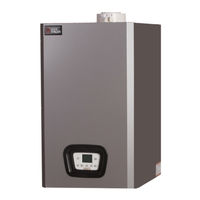
UTICA BOILERS MAC-205 Manual (139 pages)
Brand: UTICA BOILERS
|
Category: Boiler
|
Size: 39 MB
Table of Contents
Advertisement
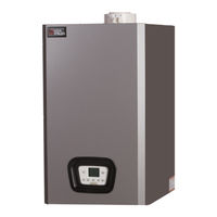
UTICA BOILERS MAC-205 Installation, Operation And Maintenance Manual (116 pages)
CONDENSING WALL MOUNTED GAS FIRED BOILER
Brand: UTICA BOILERS
|
Category: Boiler
|
Size: 33 MB
Table of Contents
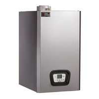
UTICA BOILERS MAC-205 User's Information Manual (9 pages)
Brand: UTICA BOILERS
|
Category: Boiler
|
Size: 1 MB
Table of Contents
Advertisement
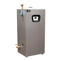
UTICA BOILERS MAC-205 User's Information Manual (9 pages)
Brand: UTICA BOILERS
|
Category: Boiler
|
Size: 0 MB