urmet domus 1723/96 Manuals
Manuals and User Guides for urmet domus 1723/96. We have 5 urmet domus 1723/96 manuals available for free PDF download: Installation Handbook, Configuration Booklet, Quick User Manual, Booklet

urmet domus 1723/96 Installation Handbook (132 pages)
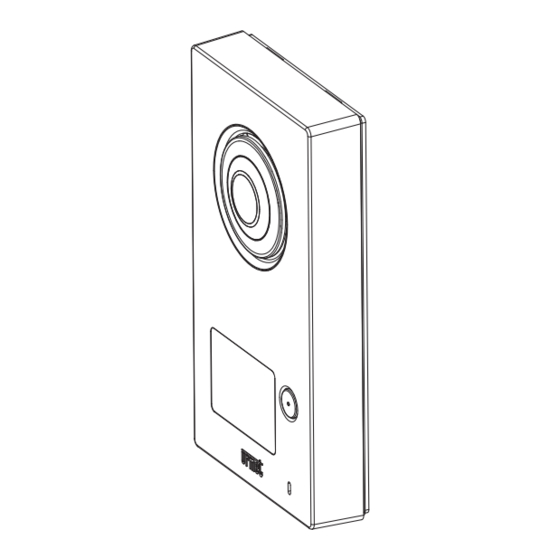
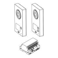
ONE- AND TWO-FAMILY 2-WIRE KIT WITH CALL FORWARDING FUNCTION
Brand: urmet domus
|
Category: Intercom System
|
Size: 10 MB
Table of Contents
-
Italiano
2 -
English
22-
Spare Parts29
-
System Type35
-
Panel ID N39
-
Français
42-
Accessoires47
-
Español
62 -
Deutsch
82-
Ersatzteile89
-
Installation93
-
Anlagentyp95
-
Installation98
-
Dutch
102-
Vlaams102
-
Extra Apparatuur107
-
Onderdelen109
-
Installatie112
-
Systeemtypen115
-
Installatie117
-
Legende Symbolen121
-
Anschlusspläne122
-
Wiring Diagram122
-
Diagram Key127
-
Legenda Schemi127
-
Legende Schema's127
-
Advertisement
urmet domus 1723/96 Installation Handbook (132 pages)
ONE- AND TWO-FAMILY 2-WIRE KIT WITH CALL FORWARDING FUNCTION
Brand: urmet domus
|
Category: Intercom System
|
Size: 11 MB
Table of Contents
-
Italiano
2 -
English
22-
Spare Parts29
-
System Type35
-
Panel ID N39
-
Français
42-
Accessoires47
-
Español
62 -
Deutsch
82-
Ersatzteile89
-
Installation93
-
Anlagentyp95
-
Installation98
-
Dutch
102-
Vlaams102
-
Extra Apparatuur107
-
Onderdelen109
-
Installatie112
-
Systeemtypen115
-
Installatie117
-
Legende Symbolen121
-
Anschlusspläne122
-
Wiring Diagram122
-
Diagram Key127
-
Legenda Schemi127
-
Legende Schema's127
-

urmet domus 1723/96 Configuration Booklet (48 pages)
ONE- AND TWO-FAMILY 2-WIRE KIT WITH CALL FORWARDING FUNCTION
Brand: urmet domus
|
Category: Intercom System
|
Size: 6 MB
Table of Contents
Advertisement

urmet domus 1723/96 Quick User Manual (40 pages)
ONE- AND TWO-FAMILY 2-WIRE KIT WITH CALL FORWARDING FUNCTION
Brand: urmet domus
|
Category: Intercom System
|
Size: 1 MB
Table of Contents

urmet domus 1723/96 Booklet (36 pages)
ONE- AND TWO-FAMILY 2-WIRE KIT WITH CALL FORWARDING FUNCTION
Brand: urmet domus
|
Category: Intercom System
|
Size: 6 MB
Table of Contents
-
Alarms17
-
Arming17
-
Alarm18
-
Deactivation19
-
Activation23
-
Deactivation26