Sign In
Upload
Manuals
Brands
Trace Engineering Manuals
Inverter
SW Series
Trace Engineering SW Series Manuals
Manuals and User Guides for Trace Engineering SW Series. We have
2
Trace Engineering SW Series manuals available for free PDF download: Owner's Manual, Installalion And Wiring Manual
Trace Engineering SW Series Owner's Manual (152 pages)
Inverter/Chargers With Revision 4.01 Software
Brand:
Trace Engineering
| Category:
Inverter
| Size: 2.88 MB
Table of Contents
Table of Contents
5
Important Safety Instructions
9
General Precautions
9
Special Notices
10
Personal Precautions
11
Introduction
13
Unit Identification
15
Model Number
15
Figure 1, Identification Label
15
Controls, Indicators and Components
17
Control Panel
17
Figure 2, SW Series Inverter/Charger
17
Figure 3, Control Panel
17
Ac Side
20
Figure 4, AC Side
20
Figure 5, Internal Components and Indicators
21
DC Side
22
Figure 6, Aux and Gen Control Relays
22
Figure 7, DC Side
22
Installation
23
Quick Install
24
Complete Install
25
Figure 8, Air Flow Intake Location
26
Figure 9, AC Input/Output Power Connection
27
Table 1, AC Input and Output Wiring Connections
27
Figure 10, Warning Label
29
Table 2, Minimum Recommended Battery Cable Size Vs. Cable Length
30
Table 3, Battery Cable to Maximum Breaker/Fuse Size
31
Figure 11, Battery to Inverter Cable Connection
32
Figure 12, Neutral-To-Ground Bond Switching: no External AC Source Connected
35
Figure 13, Neutral-To-Ground Bond Switching: External AC Source Connected
36
Figure 14, Neutral-To-Ground Bond Switching: Neutral Bonded to Ground
36
Figure 15, Multiple Point Ground System
37
Figure 16, Single Point Ground System
37
Functional Test
39
Menu System
41
Overview
41
User Menu Map
42
Setup Menu Map
43
User Menu
44
Setup Menu
52
Operation
65
Theory of Operation
65
Figure 17, Trace SW Series Inverter Simple Block Diagram
65
Figure 18, Trace SW Series Inverter Output Waveform
66
Power Vs. Efficiency
67
Figure 19, Trace SW Series Efficiency Curves
67
Inverter Capacity Vs Temperature
68
Figure 20, Inverter Capacity Vs. Temperature
68
Operating Modes
69
Inverter Mode
70
Charger Mode
72
Figure 21, Three-Stage Battery Charging
72
Figure 22, BTS (Battery Temperature Sensor)
73
Table 4, Charging Setpoints for Common Battery Types
75
Inverter/Charger Mode
77
Generator Support Mode
79
Automatic Generator Control Mode
81
Figure 23, Two Wire Start Wiring Diagram
84
Figure 24, Three Wire Start Wiring Diagram (HONDA Type)
85
Figure 25, Three Wire Start Wiring Diagram (ONAN Type)
85
Figure 26, Relay RY7 and RY8 Sequence
86
Utility Backup Mode
89
Utility Inter-Active Mode
91
Figure 27, Selling Power from a DC Charging Source; Hypothetical Time of Day Oper. History
93
Figure 28, Selling Power Stored in the Batteries; Hypothetical Time of Day Operational History
94
Figure 29, Utility Interactive Line-Tie System with Battery Backup Flow Diagram
96
Figure 30, Overvoltage Protection for Battery
97
Energy Management Mode
98
Peak Load Shaving Mode
100
In Brief
100
Low Battery Transfer (Lbx) Mode
101
Using Multiple Inverters
103
Technical Information
107
Battery Type
107
Battery Sizing
109
Table 5, Typical Wattage of Common Appliances
109
Battery Bank Sizing
110
Battery Care and Maintenance
112
Table 6, Battery Charging: Charging Setpoints
112
Table 7, Battery State of Charge Voltage
113
Battery Installation
114
Battery Hook-Up Configurations
115
Figure 31, Series Configuration: 6-Volt Battery Wiring
115
Figure 32, Series Configuration: 12-Volt Battery Wiring
115
Figure 33, Parallel Configuration: 12-Volt Battery Wiring
116
Figure 34, Series-Parallel Configuration: 6-Volt Battery Wiring
117
Figure 35, Series-Parallel Configuration: 12-Volt Battery Wiring
117
Battery Cable Inductance
118
Table 8, Battery Cable Inductance
118
Applications
119
Troubleshooting Guide
120
Inverter/Charger Terminology
123
Figure 36, AC Waveforms
124
SPECIFICATIONS and FEATURES (60 Hz Models)
126
SPECIFICATIONS and FEATURES (50 Hz Models)
127
Dimensions
128
Figure 37, SW Series Dimensions: with AC Access Covers - Showing Knockout Sizes
128
Installation Diagrams
129
Figure 38, Installation Diagram, 120 VAC, 1 Phase, Grid Connected, Generator Backup
129
Figure 39, Installation Diagram, 240 VAC, 3 Wire, Grid Connected, Generator Backup
130
User Settings Worksheets
131
Appendix
136
Options
136
Other Products
137
Reference Tables and Graphs
138
Table 9, Power Consumption of Common Appliances
138
Table 10, AWG to Metric Wire Conversion Chart
138
Figure 40, AWG Wire Size
139
Table 11, Minimum Recommended Battery Cable Size Vs. Cable Length
139
Table 12, Battery Cable to Maximum Breaker/Fuse Size
139
Table 13, Recommended Minimum AC Wire Sizes (75° C)
140
Table 14, Knockout/Hole Size to Conduit Size Required
140
Table 15, Safety Ground Wire Sizes
140
Storage Checklist
141
Warranty/Repair Information
143
Limited Warranty
143
Warranty Registration
143
Life Support Policy
143
Warranty or Repair Service Required
144
Index
145
Advertisement
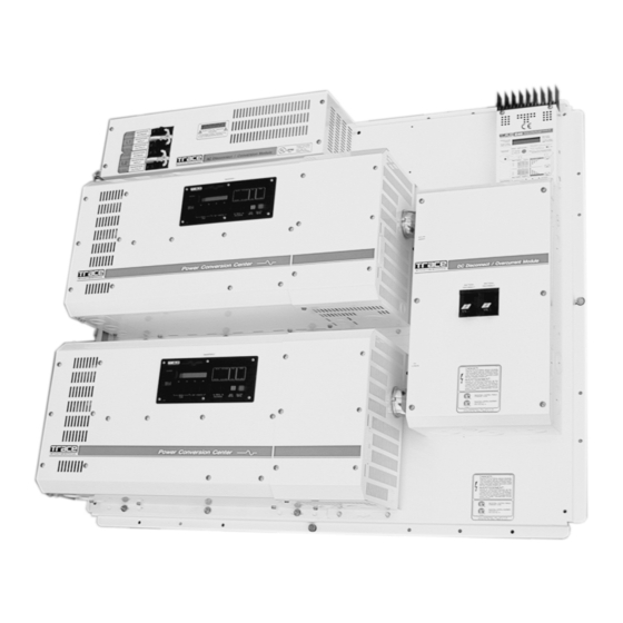
Trace Engineering SW Series Installalion And Wiring Manual (40 pages)
Integrated Power Panel
Brand:
Trace Engineering
| Category:
Inverter
| Size: 2.99 MB
Table of Contents
Table of Contents
3
Introduction
7
Installation
8
Pre-Installation
8
Tools Required
8
Hardware/Materials Required
8
Wiring
8
AC Connections
8
DC Connections
8
Grounding
8
AC Grounding
8
DC Grounding
8
Batteries
9
PV Arrays
9
Main Service Panel
9
Sub-Panel
9
AC Circuit Breakers
9
Wire Routing
9
Plywood Backing
9
Mounting
10
DC Wiring
14
PV Array
14
Battery Temperature Sensor Wiring
16
Battery Wiring
17
AC Wiring–Sw Series Dual Inverter Models
18
AC Input Wiring to the AC Bypass Box
19
AC Output Wiring to the AC Bypass Box
20
AC Input/Output Wiring (SW Single Inverter Models)
21
AC Input/Output Wiring to the AC Bypass Box
21
AC Wiring–Dr Series Dual Inverter Models
22
AC Input Wiring to the AC Bypass Box
23
AC Output Wiring to the AC Bypass Box
24
AC Input Output Wiring to the AC Bypass Box
25
Wiring Check
28
Operation
29
System Check
29
Start-Up Procedure
29
AC Disconnect Module
30
Inverter in Circuit
31
Inverter out of Circuit
31
Both AC Line and Inverter off
31
Troubleshooting
32
System Shutdown
33
Emergency Shutdown Procedure
33
Specifications
34
Service Information
36
Life Support Applications Policy
37
Warranty
38
Advertisement
Related Products
Trace Engineering SW2612E
Trace Engineering SW3024E
Trace Engineering SW4548AHC
Trace Engineering SW2612AHC
Trace Engineering SW3048AHC
Trace Engineering SW3048EHC
Trace Engineering SW3048EPV
Trace Engineering SW3048E3PH
Trace Engineering SW3024AHC
Trace Engineering SW3048APV
Trace Engineering Categories
Inverter
Controller
Remote Control
Monitor
Computer Hardware
More Trace Engineering Manuals
Login
Sign In
OR
Sign in with Facebook
Sign in with Google
Upload manual
Upload from disk
Upload from URL