Sign In
Upload
Manuals
Brands
Tormach Manuals
Industrial Electrical
1100M
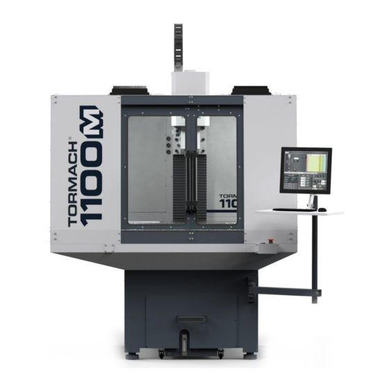
Tormach 1100M CNC Milling Machine Manuals
Manuals and User Guides for Tormach 1100M CNC Milling Machine. We have
2
Tormach 1100M CNC Milling Machine manuals available for free PDF download: Operator's Manual, Owner's Manual
Tormach 1100M Operator's Manual (305 pages)
Brand:
Tormach
| Category:
Industrial Equipment
| Size: 26 MB
Table of Contents
Table of Contents
5
Safety
21
Intended Use
22
Machine Standards
22
American National Safety Institute (ANSI)
22
Occupational Safety and Health Administration (OSHA)
22
Safety Overview
22
Safety Messages
22
Personal Injury
22
Property Damage
23
Safety Decals
23
On the Electrical Cabinet Door
23
Next to the Main Disconnect
23
On the Spindle Nose
24
Information Decals
24
Serial Number Plate
24
Machine Safety
24
General Shop Safety
24
Operational Safety
25
General
25
Tooling
26
Workholding
26
Electrical Safety
26
Noise Exposure
26
About Your Machine
29
Performance Expectations
30
Cutting Performance
30
Resolution and Accuracy
30
Machine Specifications
31
Site Requirements
33
General Site and Space Requirements
34
Site Requirements
34
Space Requirements
34
Operator Workstation Reference
34
Electrical and Power Requirements
35
Electrical Requirements
35
Power Requirements
35
Options for Non-Conforming Sites
35
Installation
37
Visual Installation Guide
38
Before You Begin
39
Installation Tools and Items
39
Move the Pallet
39
Assemble the Machine Stand
39
Unpack the Machine Crate
41
Install Core Components
42
Install the Y-Axis Bellows Spacers
42
Install the Axis Motors
43
Y-Axis Motor
43
X-Axis Motor
44
Z-Axis Motor
44
Lift and Move the Machine
45
Required Tools
45
Before You Begin
45
Assemble the Lifting Bar Kit
45
Connect the Machine for Lifting
46
Lift the Machine
46
Install the Tool Tray and Drip Guard
47
Install the Controller
47
Install the Controller Arm
48
Install the Monitor
49
Make Monitor Connections
49
Install the Pathpilot Controller
50
Set up the Pathpilot Operator Console
50
Install the Oiler
51
Make Automatic Oiler Connections
51
Make Manual Oiler Connections
52
Set up the Manual Oiler
52
Verify the Installation
52
Power on the Machine
52
Power off the Machine
54
Verify Limit Switch Function
54
Verify Axes Function
54
Verify Spindle Function
55
Install Accessory Components
56
Set up the Automatic Oiler
56
Look for Leaks and Clear the Lines
56
Specify the Interval Time
56
Specify the Actuation Time
57
Install the Power Drawbar
57
Required Tools
57
Air Requirements
57
Installation
57
Prepare the Machine
58
Disassemble the Original Drawbar
58
Assemble the Power Drawbar
59
Install the FRL
61
Set up the FRL
62
Make Air Connections
62
Adjust the Power Drawbar
64
Adjust the Drawbar Tension
64
About Drawbar Tension
64
Adjust the Initial Setup
65
Install the Flood Coolant Kit
66
Adjust the Coolant Pump Motor Strapping
66
Set up the Flood Coolant Kit
66
Install the Automatic Tool Changer (ATC)
67
Required Tools
68
Required Tools for Installation
68
Required Tools for Verification
68
Air Requirements
68
Before You Begin
68
Disassemble the Power Drawbar Button
68
Install the Air Cylinder
69
Mount the Automatic Tool Changer (ATC) Bracket
69
Install the Main Assembly
70
Level the Automatic Tool Changer (ATC)
70
Prepare the Machine
70
Examine Perpendicularity in the y Direction
71
Examine Perpendicularity in the X Direction
71
Examine the Alignment of the Carousel Door Opening
71
Make Air Connections
73
Make Electrical Connections
73
Verify the Installation
73
Adjust the Power Drawbar
74
Adjust the Drawbar Tension
74
About Drawbar Tension
75
Adjust the Initial Setup
75
Adjust the Tool Tray Load Position
76
Verify the Alignment
77
Set the Tool Change Height
77
Adjust for Rotational Play
77
Install the 4Th Axis
78
Install the M/MX A-Axis Driver (PN 38954)
78
Set the Driver DIP Switches
78
Install the A-Axis Motor Driver
79
Set up the 6 In. or 8 In. Rotary Table
79
Required Tools
79
Unpack the 4Th Axis
80
Lubricate the Rotary Table
80
Adjust the Backlash
80
To Set the Backlash by Positioning the Backlash Adjustment Screw
81
To Set the Backlash by the Numbers
81
Mount the Rotary Table
81
Set up the Microarc 4
82
Required Tools
82
Install in Machine
82
Center the Chuck Mounting Plate
83
Verify the Installation
84
Install the Chip Pans
84
Install the Backsplash and Splash Guard
85
Install the Enclosure
86
Before You Begin
86
Required Tools
87
Install the Enclosure Panels
87
Install the Left Rear Panel
87
Install the Left Side Panel
87
Install the Left Side Window Retainers
87
Install the Left Front Panel
88
Install the Enclosure Splice Plate
88
Install the Right Rear Panel
88
Install the Right Side Panel
88
Install the Right Side Window Retainers
88
Install the Right Front Panel
89
Install the Left Top Panel
89
Install the Right Top Panel
90
Install the Upper Front Panel
90
Install the Front Lower Panel
90
Install the Rear Splash Shield
91
Assemble the Linear Rails
91
Install the Linear Assemblies
91
Assemble the Front Doors
92
Install the Front Door Assemblies
93
Install the Door Latch
94
Install the Floodlights
94
Install the Side Windows
94
Install the Access Panel
95
Install the Stainless Steel Wear Guard
96
Use the Maintenance Labels
96
Write the Date on the Maintenance Labels
96
Replace the Windows
97
Set up the Door Lock Switch Kit (Optional)
97
Install the Door Lock Switch Kit
97
Update Pathpilot
99
Download and Install an Update File from the Controller
99
Install an Update File from a USB Drive
99
Enable the Door Lock Switch Kit
100
Install the Pathpilot Operator Console
100
Required Tools
101
Prepare the Machine
101
Remove the Right Side Window
101
Remove the Operator Box
101
Install the Mount Arm
101
Mount the Console
102
Assemble the Controller and Keyboard Tray
102
Lift and Secure the Controller Assembly
104
Make Electrical Connections
105
Reassemble the Machine
107
Pathpilot Operator Console Drill Template
108
Set up the Pathpilot Controller
109
Specify the Date and Time
109
Specify the Keyboard Language
109
Configure the Optional Touch Screen Kit
109
Update Pathpilot
109
System Basics
111
System Reference
112
Machine Table
112
Spindle
112
About the Spindle
112
Axes
112
Basic Controls Reference
112
Machine Controls
112
Pathpilot Interface
113
Pathpilot Interface Overview
115
About Pathpilot
116
Notebook Section
116
Main Tab
116
File Tab
116
Settings Tab
117
Offsets Tab
117
Conversational Tab
117
Probe Tab
118
Status Tab
118
Persistent Controls
118
Program Control Area
118
Position Status Area
119
Manual Control Area
119
Keyboard Shortcuts
119
Manage Pathpilot Versions
119
Download and Install an Update File from the Controller
119
Install an Update File from a USB Drive
120
Install a Previous Version of an Update File
120
Pathpilot Tools and Features
123
Create and Load G-Code Files
124
Load G-Code
124
Transfer Files to and from the Controller
124
About System Files
124
Preview G-Code Files
124
Access Recent G-Code Files
125
Close the Current Program
125
Edit G-Code
125
Edit G-Code with a Text Editor
125
Edit G-Code with Conversational Programming
125
Change the Step Order
126
Create a New Job Assignment
126
Load an Existing G-Code File
126
Edit a Job Assignment
126
Read G-Code
126
Expand the G-Code Tab
126
About the G-Code Tab
126
Search in the Code
126
Set a New Start Line
127
Lead-In Moves
127
Change the View of the Tool Path Display
128
About the Tool Path Display
128
Use Conversational Programming
129
About Conversational Programming
129
Create a Face on a Part
129
About Facing
130
Facing in Pathpilot
130
Facing Reference
130
Create a Profile on a Part
130
About Profiling
131
Profiling in Pathpilot
131
Profiling Reference
132
Create a Pocket on a Part
132
About Pockets
133
Creating Pockets in Pathpilot
133
About Circular Pockets
133
About Rectangular Pockets
133
Create Hole Locations on a Part (Drill/Tap)
134
About Drilling and Tapping
135
Drilling and Tapping in Pathpilot
135
Create a Drilling Sequence
135
Create a Tapping Sequence
136
Drilling and Tapping Reference
136
Create Threads on a Part
136
About Thread Milling
137
Thread Milling in Pathpilot
137
Thread Milling Reference
137
Create Text to Engrave on a Part
138
About Engraving
138
Import a DXF File
138
Working with Layers and Shapes
139
Change the Layer or Shape Cut Order
139
Adjust the Tree View Window
139
Working in the Preview Window
139
Machine Settings and Accessories
139
Enable an Internet Connection
140
Connect to Dropbox
140
Enable Automatic Updates
141
Change the Network Name
142
Select the Spindle Type
142
Change the Screen Orientation
142
About Portrait Screen Layout
143
Specify the Tool Change Method
144
About Automatic Tool Changes
144
About Manual Tool Changes
144
Disable Limit Switches
144
Limit G30 Moves
145
About G30
145
Enable the On-Screen Keyboard
145
About Soft Keyboards
145
Enable the USB M-Code I/O Interface Kit
146
Enable Tooltips
146
Enable the Door Lock Switch Kit
146
Enable Feeds and Speeds Suggestions in Conversational Routines
147
Specify Probing and Tool Measuring Options
147
Use the Rapidturn Interface
147
Specify the 4Th Axis Rotary Type
147
Enable the 4Th Axis Homing Kit
147
Use a USB Camera
148
About USB Cameras
148
Manual Recording
148
Automatic E-Stop Loop Recording ("Dashcam")
149
Review Video and Image Files
149
File Naming Convention
150
G-Code Commands
150
File Naming Conventions
150
Use M01 to Take Pictures
150
Set up G-Code Programs
151
Use a Probe with Pathpilot
151
Set up the Probe
151
Use a Probe to Find a Feature's Location
151
Use a Probe to Set Work Offset Zeroes
151
Set the X and y Work Offset Zero on the Corner of a Feature
151
Set the Work Offset Zeroes on a Feature
151
Use a Probe to Find the Center of a Feature
152
Find the Center of a Pocket
152
Find the Center of a Slot
152
Find the Center of a Rectangular Boss
152
Find the Center of a Circular Boss
152
Find the Center Rotation of an A-Axis
153
Set Tool Length Offsets
153
About Tool Offsets
153
Touch off the Tool Length Offsets
154
Set a Known Reference Height
154
Measure Tools Using a Known Reference Height
154
Use an Electronic Tool Setter (ETS) to Measure Tools
155
Use a Height Gauge to Measure Tools
155
Set Work Offsets
156
About Work Offsets
156
View Work Offsets
156
View Available G-Code Modes
157
Run G-Code Programs
157
Bring the Machine out of Reset
157
About Reset Mode
157
View the Active Axis to Jog
157
Jog the Machine
157
Jog in Continuous Velocity Mode
158
Jog in Step Mode
158
View the Current Machine Position
158
Reference the Machine
158
About Referencing
159
Start a Program
159
About Cycle Start
159
Cycle Start Reference
159
Stop Machine Motion
159
Operate the Coolant Pump
159
About Coolant
159
View the Active G-Code Modes
160
View the Distance to Go
160
About Distance to Go
160
Control G-Code Programs
160
Use the Feed Hold Function
160
About Feed Hold
160
Use the Feed Rate Override Function
161
About Feed Rate Override
161
Use M01 Break Mode
161
About M01 Break
161
Display Information and Capture Images During an M00 or M01 Break
161
Display Information with Images
161
Display Information with Text
162
Capture Images with a USB Camera
162
Use the Maxvel Override Function
162
About Maxvel Override
162
Use Single Block Mode
162
About Single Block
162
Use the Spindle Override Function
163
About Spindle Override
163
Change the Feed Rate
163
About Feed Rates
163
Change the Spindle Speed
163
About Spindle Controls
164
Spindle Controls Reference
164
Change the Tool Number
164
About M6 G43
164
Use a G30 Position
164
About G30
165
View the Tool Length
165
Manually Enter Commands
165
About the MDI Line DRO Field
165
Admin Commands Reference
165
Copy Recently Entered Commands
166
Use Feeds and Speeds Suggestions
166
Refresh DRO Field Values
167
Use Additional Provided Information
167
Create Tool Descriptions
167
Manually Enter Tool Descriptions
168
Automatically Generate Tool Descriptions
168
Tool Keywords Reference
168
Use Cycle Counters (M30 and M99)
169
Monitor Cycle Counters
169
Change Cycle Counter Values
169
System File Management
170
Manage System Files
170
About System Files
170
Create Backup Files
170
About Backup Files
171
Restore Backup Files
171
Import and Export the Tool Table
172
Import a .Csv File
172
Export the Tool Table as a .Csv File
172
Basic Operations
175
Start the Machine
176
Reference the Machine
176
About Referencing
176
Jog the Machine
176
About Jogging
177
About Continuous Velocity Jogging
177
About Step Jogging
177
Jog Controls Reference
177
Jogging in Pathpilot
177
Jogging with the Keyboard
177
Jogging with the (Optional) Jog Shuttle
177
Manually Control the Spindle
178
Change the Spindle Speed Range
178
About the Spindle
178
Spindle Controls Reference
179
Load G-Code
179
Set up Tooling
179
Install a Tool in a Set Screw Tool Holder
179
Install a Tool in an er Collet Tool Holder
179
Install a Drill Chuck in a Jacobs Taper Arbor
180
Set Tool Length Offsets
180
About Tool Offsets
180
Touch off the Tool Length Offsets
180
Set a Known Reference Height
181
Measure Tools Using a Known Reference Height
181
Use an Electronic Tool Setter (ETS) to Measure Tools
182
Use a Height Gauge to Measure Tools
182
Set Work Offsets
182
About Work Offsets
183
Operate the Coolant Pump
183
About Coolant
183
First Part Tutorial
185
About this Tutorial
186
Before You Begin
186
Required Items and Tools
186
Set up Tooling
186
Install a Tool in a Set Screw Tool Holder
186
Install a Tool in an er Collet Tool Holder
186
Set up the Machine
187
About Referencing
187
Mount the Workpiece
187
Set the Work Offsets
187
Set the Z Zero
187
Set the X/Y Zeroes
188
About Work Offsets
188
About True Positive Tool Length
189
About X/Y Part Zeroes
189
Set Tool Offsets
189
Touch off the Tool Offsets
189
Measure Tools Using a Known Reference Height
189
Complete the Milling Operations
189
Create a Pocket
190
Load the Tool
190
Write the G-Code with Conversational
190
Run the Program
191
Engrave the Text
191
Write the G-Code with Conversational
191
Run the Program
192
Programming
193
Programming Overview
194
About G-Code Programming Language
194
G-Code Formatting Reference
194
Line Numbers
194
Words
194
Letters
195
Values
195
Order of Execution
196
Modal Groups
197
Comments
198
Supported G-Codes Reference
198
Programming G-Code
199
About the Examples Used
199
Rapid Linear Motion (G00)
199
Linear Motion at Feed Rate (G01)
200
Arc at Feed Rate (G02 and G03)
200
Radius Format Arc
200
Center Format Arc
201
Arc in XY Plane
201
Arc in XZ Plane
201
Arc in YZ Plane
201
Dwell (G04)
202
Set Offsets (G10)
202
Set Tool Table (G10 L1)
202
Set Coordinate System (G10 L2)
203
Set Tool Table (G10 L10)
203
Set Tool Table (G10 L11)
203
Set Coordinate System (G10 L20)
203
Plane Selection (G17, G18, G19)
204
Length Units (G20 and G21)
204
Return to Predefined Position (G28 and G28.1)
204
Return to Predefined Position (G30 and G30.1)
204
Automatically Measure Tool Lengths with an ETS (G37 and G37.1)
204
Move to G37 Position over ETS (G37.1)
204
Move and Measure Tool Length (G37)
205
Straight Probe (G38.X)
205
Use the Straight Probe Command
206
Cutter Compensation (G40, G41, G42)
206
Dynamic Cutter Compensation (G41.1 and G42.1)
207
Apply Tool Length Offset (G43)
207
Engrave Sequential Serial Number (G47)
207
Cancel Tool Length Compensation (G49)
208
Absolute Coordinates (G53)
208
Select Work Offset Coordinate System (G54 to G54.1 P500)
208
Set Exact Path Control Mode (G61)
208
Set Blended Path Control Mode (G64)
208
Distance Mode (G90 and G91)
208
Arc Distance Mode (G90.1 and G91.1)
209
Temporary Work Offsets (G92, G92.1, G92.2, and G92.3)
209
Feed Rate Mode (G93, G94, and G95)
209
Spindle Control Mode (G96 and G97)
210
Programming Canned Cycles
210
Canned Cycles Reference
210
High Speed Peck Drill (G73)
211
Cancel Canned Cycles (G80)
212
Drilling Cycle (G81)
212
Simple Drilling Cycle (G82)
213
Peck Drilling Cycle (G83)
213
Tapping Cycle (G84)
213
Boring Cycle (G85)
213
Boring Cycle (G86)
214
Boring Cycle (G88)
214
Boring Cycle (G89)
214
Programming M-Code
214
Supported M-Codes Reference
214
Program Stop and Program End (M00, M01, M02, and M30)
215
Display Information and Capture Images During an M00 or M01 Break
215
Display Information with Images
215
Display Information with Text
215
Capture Images with a USB Camera
216
Spindle Control (M03, M04, and M05)
216
Tool Change (M06)
216
Coolant Control (M07, M08, and M09)
216
Override Control (M48 and M49)
216
Feed Override Control (M50)
216
Spindle Speed Override Control (M51)
216
Set Current Tool Number (M61)
217
Set Output State (M64 and M65)
217
Wait on Input (M66)
217
USB Camera Control (M301, M302, M303)
217
Programming Input Codes
218
Feed Rate (F)
218
Spindle Speed (S)
218
Change Tool Number (T)
218
Advanced Programming
218
Parameters
218
Parameters Reference
218
Parameter Syntax
218
Parameter Scope
219
Behavior of Uninitialized Parameters
219
Parameter Mode
219
Persistence and Volatility
219
Intended Use
219
Numbered Parameters Reference
219
Read-Only Parameters
219
Subroutine Parameters Reference
220
Named Parameters Reference
220
Expressions
220
Binary Operators Reference
220
Functions Reference
221
Subroutines
221
Subroutines Reference
221
Conditional Subroutines Reference
222
If/Endif
222
If/Elseif/Else/Endif
222
Repeating Subroutines Reference
223
Looping Subroutines Reference
223
Do/While
223
While/Endwhile
223
Machine Maintenance
225
Maintenance Safety
226
All Maintenance Procedures
226
Swarf Maintenance Procedures
226
Coolant Maintenance Procedures
226
Maintenance Schedules
226
Daily
226
Weekly
226
Monthly
226
Semi-Annually
226
Annually
227
Regular Maintenance
227
Clean the Way Covers
227
Clean the Coolant System
227
About Cutting Fluid
227
Cutting Fluid Reference
227
Examine the Drawbar
228
Examine the Enclosure Windows
228
Lubricate the Machine
228
About the Manual Oiler
228
About the Automatic Oiler
229
Lubrication System Reference
229
Examine the Spindle Belt
229
Examine the Tormach Tooling System (TTS) Collet
229
Prevent Rust
229
Remove Rust
229
Troubleshooting
231
Troubleshooting Safety
232
Getting Help
232
Required Tools
232
Frequently Found Problems
233
Electrical Service
234
Power Distribution Subsystem
234
The Controller Won't Power on
234
The Coolant Pump Won't Run
235
Control Power Subsystem
236
The Machine Won't Power on
236
Axes Drive Subsystem
237
All Axes Won't Move When Commanded
238
One Axis Won't Move (or Only Moves in One Direction), and Other Axes Move
238
Motor Resistance Reference
241
DC-BUS Power Distribution Reference
241
Axis Movement Is Noisy
241
Can't Reference All Axes
243
Limit Switch Function Reference
244
Lost Motion on Axis Travel
245
Spindle Drive Subsystem
247
The Spindle Won't Turn
248
Run and Direction Commands Reference
251
Spindle VFD Trip Reference
251
Machining Operations Are Loud ("Chattery")
252
Can't Load or Unload a Tool, or the Spindle's Drawbar Drags against the Power Drawbar Cylinder's Piston Bolt
253
Operator Console Troubleshooting
254
The Screen Doesn't Respond to Touch Inputs
254
The Screen Doesn't Display an Image or Respond to Power Button
255
The Screen Is Scrambled or Illegible
255
The Knobs Don't Respond
256
The Buttons Don't Respond
257
Diagrams and Parts Lists
259
Base Machine Exploded View
260
Base Machine Parts List
261
Spindle Head Exploded View
262
Spindle Head Parts List
263
TTS Power Drawbar Cylinder Exploded View
265
TTS Power Drawbar Cylinder Assembly Parts List
266
Power Drawbar Push Button Exploded View
267
Power Drawbar Push Button Parts List
268
Spindle Motor Cover Exploded View
269
Spindle Motor Cover Parts List
270
X-Axis Assembly Exploded View
271
X-Axis Assembly Parts List
272
Y-Axis Assembly Exploded View
274
Y-Axis Assembly Parts List
275
Y-Axis Saddle Exploded View
277
Y-Axis Saddle Parts List
278
X-Y Axis Assembly Exploded View
279
X-Y Axis Assembly Parts List
280
Z-Axis Assembly Exploded View
281
Z-Axis Assembly Parts List
282
Enclosure Exploded View
284
Enclosure Parts List
285
Lubrication/Oil System Diagram
287
Pneumatic Schematics
289
Power Drawbar Pneumatics
290
Automatic Tool Changer (ATC) Pneumatics
291
Electrical Schematics
293
Vac Power (Sheet 1)
294
VDC Controls (Sheet 2)
295
Axis Drive Bus (Sheet 3)
296
Spindle Drive (Sheet 4)
297
Machine Control Board (Sheet 5)
298
Limit/Door Switches (Sheet 6)
299
Accessory and Auxiliary Power (Sheet 7)
300
Grounds (Sheet 8)
301
Electrical Panel Layout and Fuse Table (Sheet 9)
302
Operator Box Layout (Sheet 10)
303
Wiring Table (Sheet 11)
304
Operator Console Schematic
305
Advertisement
Tormach 1100M Owner's Manual (28 pages)
Power Drawbar
Brand:
Tormach
| Category:
Industrial Electrical
| Size: 7 MB
Table of Contents
Table of Contents
3
Complete the Following Steps in the Order Listed
3
Required Tools
3
Air Requirements
3
Install the Power Drawbar
3
Prepare the Machine
4
Disassemble the Original Drawbar
4
Assemble the Power Drawbar
6
Install the FRL
12
Set up the FRL
13
Make Air Connections
14
Adjust the Power Drawbar
17
Advertisement
Related Products
Tormach 1300PL
Tormach Slant-PRO 15L
Tormach 1100MX
Tormach 1500MX
Tormach Categories
Industrial Equipment
Power Tool
Enclosure
Racks & Stands
Lathe
More Tormach Manuals
Login
Sign In
OR
Sign in with Facebook
Sign in with Google
Upload manual
Upload from disk
Upload from URL