Sign In
Upload
Manuals
Brands
Tormach Manuals
Industrial Equipment
1500MX
Tormach 1500MX Manuals
Manuals and User Guides for Tormach 1500MX. We have
1
Tormach 1500MX manual available for free PDF download: Operator's Manual
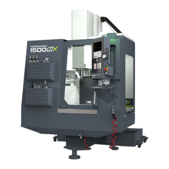
Tormach 1500MX Operator's Manual (288 pages)
Brand:
Tormach
| Category:
Industrial Equipment
| Size: 13 MB
Table of Contents
Table of Contents
5
Safety
19
Intended Use
20
Machine Standards
20
American National Safety Institute (ANSI)
20
Occupational Safety and Health Administration (OSHA)
20
Safety Overview
20
Safety Messages
20
Personal Injury
20
Property Damage
21
Safety Decals
21
On the Electrical Cabinet Door
21
Next to the Main Disconnect
22
On the Spindle Nose
22
Information Decals
23
Serial Number Plate
23
Machine Safety
23
General Shop Safety
23
Operational Safety
24
General
24
Tooling
24
Workholding
25
Electrical Safety
25
Noise Exposure
25
Operating Modes Reference
25
Run Mode (Mode 1)
25
Setup Mode (Mode 2)
26
Mode Constraints
26
Automatic Tool Changer (ATC) Constraints
27
About Your Machine
29
Machine Specifications
30
Site Requirements
33
General Site and Space Requirements
34
Site Requirements
34
Space Requirements
34
Operator Workstation Reference
34
Electrical and Power Requirements
34
Electrical Requirements
34
Power Requirements
34
Space Planning Drawing - 1500MX
36
Electrical Site Plan - 1500MX
37
Installation
39
Before You Begin
40
Inspect the Items Delivered
40
Machine Configuration
40
Installation Tools and Items
40
Move the Pallet
40
Unpack the Machine Crate
41
Self-Assembled Installation
42
Install the Enclosure
42
Before You Begin
43
Helpful Tips for Installation
43
Install the Chip Trays
43
Required Tools and Items
43
Install the Enclosure Panels
46
Assemble the Door
52
Install the Door Latch
55
Secure Panel and Door Screws
55
Install the Door Latch Push Button
56
Install the Components
57
Install the Lights
57
Install the Air Gun
58
Install the Windows
59
Assemble the Console
60
Set up the Pathpilot Controller
61
Specify the Date and Time
61
Specify the Keyboard Language
61
Update Pathpilot
61
Factory-Assembled Machine Setup
62
Set up the Pathpilot Controller
62
Specify the Date and Time
62
Specify the Keyboard Language
62
Update Pathpilot
62
Set up the Flood Coolant Kit
63
Install the Flood Coolant Pump
63
Required Tools
63
Unpack the Coolant Tank Crate
63
Install the Flood Coolant Filter
64
Make Coolant Connections
64
Verify the Installation
65
Power on the Machine
65
Verify Axes Function
67
Verify Spindle Function
67
Power off the Machine
67
Install Accessory Components
68
Install the Automatic Tool Changer
68
Prepare the Machine
68
Required Tools
68
Unpack the ATC Box
68
Assemble the ATC
70
Install the ATC Electrical Cabinet
72
Level the ATC
75
Adjust the Tool Alignment and Set the Tool Tray Height and Encoder Position
77
Install the Flood Coolant Kit
78
Required Tools
78
Unpack the Coolant Tank Crate
78
Install the Flood Coolant Filter
79
Install the Flood Coolant Pump
79
Install the Coolant Manifold
80
Install the Y-Axis Washdown Nozzle
80
Install the Flood Coolant Ring
82
Install the Manual Sprayer
83
Make Coolant Connections
86
Install the Automatic Chip Tray Washdown Kit
86
Before You Begin
86
Install the Coolant Hoses and Fittings
87
Install the Washdown Coolant Filter
87
Install the Washdown Pump
87
Required Tools
87
Install the Washdown Bars
88
Make Connections
88
Install the MQL Kit
89
Remove the Tubing from the Pump
89
Required Tools
89
Route the Tubing
90
Mount the Pump
91
Install the Microarc
93
Install the A-Axis Driver Install the Microarc 6 in the Machine
93
Install the Probe and Tool Setter
98
Before You Begin
98
Notes
98
Required Tools
98
Wireless Receiver Installation
98
Wireless Probe Installation and Setup
99
Adjust Probe Tip Concentricity
100
Set Probe Length and Diameter
100
Probe Status Lights Reference
102
Tool Setter Installation and Setup
102
Align the Tool Setter's Stylus
103
Reference the Tool Setter
104
Set G37 Position
104
System Basics
105
System Reference
106
Machine Table
106
Spindle
106
About the Spindle
106
Axes
106
Basic Controls Reference
106
Machine Controls
106
Pathpilot Interface
107
Tormach® 2024
107
Pathpilot Interface Overview
109
About Pathpilot
110
Notebook Section
110
Main Tab
110
File Tab
110
Settings Tab
111
Offsets Tab
111
Conversational Tab
111
Probe Tab
111
Status Tab
112
Persistent Controls
112
Program Control Area
112
Position Status Area
112
Manual Control Area
113
Keyboard Shortcuts
113
Manage Pathpilot Versions
113
Download and Install an Update File from the Controller
113
Install an Update File from a USB Drive
114
Install a Previous Version of an Update File
114
Pathpilot Tools and Features
117
Create and Load G-Code Files
118
Load G-Code
118
About System Files
118
Preview G-Code Files
118
Transfer Files to and from the Controller
118
Access Recent G-Code Files
119
Close the Current Program
119
Edit G-Code
119
Edit G-Code with a Text Editor
119
Edit G-Code with Conversational Programming
119
Change the Step Order
120
Create a New Job Assignment
120
Edit a Job Assignment
120
Load an Existing G-Code File
120
Read G-Code
120
About the G-Code Tab
120
Expand the G-Code Tab
120
Search in the Code
120
Lead-In Moves
121
Set a New Start Line
121
About the Tool Path Display
122
Change the View of the Tool Path Display
122
Use Conversational Programming
123
About Conversational Programming
123
Create a Face on a Part
123
About Facing
124
Create a Profile on a Part
124
Facing in Pathpilot
124
Facing Reference
124
About Profiling
125
Profiling in Pathpilot
125
Create a Pocket on a Part
126
Profiling Reference
126
About Circular Pockets
127
About Pockets
127
About Rectangular Pockets
127
Creating Pockets in Pathpilot
127
Create Hole Locations on a Part (Drill/Tap)
128
About Drilling and Tapping
129
Create a Drilling Sequence
129
Drilling and Tapping in Pathpilot
129
Create a Tapping Sequence
130
Create Threads on a Part
130
Drilling and Tapping Reference
130
About Thread Milling
131
Thread Milling in Pathpilot
131
Thread Milling Reference
131
About Engraving
132
Create Text to Engrave on a Part
132
Import a DXF File
132
Adjust the Tree View Window
133
Change the Layer or Shape Cut Order
133
Working in the Preview Window
133
Working with Layers and Shapes
133
Machine Settings and Accessories
133
Change the Network Name
134
Select the Spindle Type
134
Specify the Tool Change Method
134
About Automatic Tool Changes
134
About Manual Tool Changes
134
Enable Accessories
134
Specify Probing and Tool Measuring Options
134
Enable the USB M-Code I/O Interface Kit
135
Enable an Internet Connection
135
Connect to Dropbox
135
Enable Automatic Updates
137
Set up G-Code Programs
137
Use a Probe with Pathpilot
137
Set the X and y Work Offset Zero on the Corner of a Feature
137
Set up the Probe
137
Use a Probe to Find a Feature's Location
137
Use a Probe to Set Work Offset Zeroes
137
Find the Center of a Pocket
138
Find the Center of a Rectangular Boss
138
Find the Center of a Slot
138
Set the Work Offset Zeroes on a Feature
138
Use a Probe to Find the Center of a Feature
138
Find the Center of a Circular Boss
139
Find the Center Rotation of an A-Axis
139
Set Tool Length Offsets
139
About Tool Offsets
140
Measure Tools Using a Known Reference Height
140
Set a Known Reference Height
140
Touch off the Tool Length Offsets
140
Use an Electronic Tool Setter (ETS) to Measure Tools
141
Measure Tools Using a Known Reference Height
142
Set a Known Reference Height
142
Use a Tool Height Setter to Measure Tools
142
Verify the Calibration of the Tool Height Setter
142
Set Work Offsets
143
About Work Offsets
143
View Work Offsets
144
View Available G-Code Modes
144
Run G-Code Programs
144
Bring the Machine out of Reset
144
About Reset Mode
144
View the Active Axis to Jog
145
Jog the Machine
145
Jog in Continuous Velocity Mode
145
Jog in Step Mode
145
View the Current Machine Position
146
Reference the Machine
146
About Referencing
146
Start a Program
146
About Cycle Start
146
Cycle Start Reference
146
Stop Machine Motion
147
View the Active G-Code Modes
147
View the Distance to Go
147
About Distance to Go
147
Control G-Code Programs
147
Use the Feed Hold Function
147
About Feed Hold
147
Use the Feed Rate Override Function
148
About Feed Rate Override
148
Use M01 Break Mode
148
About M01 Break
148
Use the Maxvel Override Function
148
About Maxvel Override
149
Use Single Block Mode
149
About Single Block
149
Use the Spindle Override Function
149
About Spindle Override
149
Change the Feed Rate
149
About Feed Rates
150
Change the Spindle Speed
150
About Spindle Controls
150
Change the Tool Number
150
About M6 G43
150
Use a G30 Position
150
About G30
151
View the Tool Length
151
Manually Enter Commands
151
About the MDI Line DRO Field
151
Admin Commands Reference
151
Copy Recently Entered Commands
152
Limit G30 Moves
152
About G30
152
Use Feeds and Speeds Suggestions
152
Refresh DRO Field Values
153
Use Additional Provided Information
153
Create Tool Descriptions
154
Enable Feeds and Speeds Suggestions in Conversational Routines
154
Manually Enter Tool Descriptions
154
Automatically Generate Tool Descriptions
155
Tool Keywords Reference
155
System File Management
156
Manage System Files
156
About System Files
156
Create Backup Files
156
About Backup Files
157
Restore Backup Files
157
Import and Export the Tool Table
158
Export the Tool Table as a .Csv File
158
Import a .Csv File
158
Basic Operations
161
Start the Machine
162
Reference the Machine
162
About Referencing
162
Jog the Machine
162
About Jogging
163
About Continuous Velocity Jogging
163
About Step Jogging
163
Jog Controls Reference
163
Jogging in Pathpilot
163
Jogging with the (Optional) Jog Shuttle
163
Jogging with the Keyboard
163
Manually Control the Spindle
164
About the Spindle
164
Load G-Code
164
Set up Tooling
164
Install a Tool in a Set Screw Tool Holder
165
Install a Tool in an er Collet Tool Holder
165
Install a Drill Chuck in a Jacobs Taper Arbor
165
Set Tool Length Offsets
165
About Tool Offsets
166
Touch off the Tool Length Offsets
166
Set a Known Reference Height
166
Measure Tools Using a Known Reference Height
167
Use an Electronic Tool Setter (ETS) to Measure Tools
167
Use a Tool Height Setter to Measure Tools
168
Set a Known Reference Height
168
Verify the Calibration of the Tool Height Setter
168
Measure Tools Using a Known Reference Height
169
Set Work Offsets
169
About Work Offsets
170
Operate the Coolant Pump
170
About Coolant
170
Programming
171
Programming Overview
172
About G-Code Programming Language
172
G-Code Formatting Reference
172
Line Numbers
172
Words
172
Letters
173
Values
173
Order of Execution
174
Modal Groups
175
Comments
176
Supported G-Codes Reference
176
Programming G-Code
177
About the Examples Used
177
Rapid Linear Motion (G00)
177
Linear Motion at Feed Rate (G01)
178
Arc at Feed Rate (G02 and G03)
178
Radius Format Arc
178
Arc in XY Plane
179
Arc in XZ Plane
179
Arc in YZ Plane
179
Center Format Arc
179
Dwell (G04)
180
Set Offsets (G10)
180
Set Tool Table (G10 L1)
180
Set Coordinate System (G10 L2)
181
Set Coordinate System (G10 L20)
181
Set Tool Table (G10 L10)
181
Set Tool Table (G10 L11)
181
Plane Selection (G17, G18, G19)
182
Length Units (G20 and G21)
182
Return to Predefined Position (G28 and G28.1)
182
Return to Predefined Position (G30 and G30.1)
182
Automatically Measure Tool Lengths with an ETS (G37 and G37.1)
182
Move to G37 Position over ETS (G37.1)
182
Move and Measure Tool Length (G37)
183
Straight Probe (G38.X)
183
Use the Straight Probe Command
184
Cutter Compensation (G40, G41, G42)
185
Dynamic Cutter Compensation (G41.1 and G42.1)
185
Apply Tool Length Offset (G43)
185
Engrave Sequential Serial Number (G47)
185
Cancel Tool Length Compensation (G49)
186
Absolute Coordinates (G53)
186
Select Work Offset Coordinate System (G54 to G54.1 P500)
186
Set Exact Path Control Mode (G61)
186
Set Blended Path Control Mode (G64)
186
Distance Mode (G90 and G91)
187
Arc Distance Mode (G90.1 and G91.1)
187
Temporary Work Offsets (G92, G92.1, G92.2, and G92.3)
187
Feed Rate Mode (G93, G94, and G95)
187
Spindle Control Mode (G96 and G97)
188
Programming Canned Cycles
188
Canned Cycles Reference Supported Canned Cycles
188
High Speed Peck Drill (G73)
190
Cancel Canned Cycles (G80)
190
Drilling Cycle (G81)
190
Simple Drilling Cycle (G82)
191
Peck Drilling Cycle (G83)
191
Boring Cycle (G85)
191
Boring Cycle (G86)
192
Boring Cycle (G88)
192
Boring Cycle (G89)
192
Programming M-Code
192
Supported M-Codes Reference
192
Program Stop and Program End (M00, M01, M02, and M30)
193
Spindle Control (M03, M04, and M05)
193
Tool Change (M06)
193
Coolant Control (M07, M08, and M09)
193
Override Control (M48 and M49)
194
Feed Override Control (M50)
194
Spindle Speed Override Control (M51)
194
Set Current Tool Number (M61)
194
Set Output State (M64 and M65)
194
Wait on Input (M66)
194
Chip Conveyor Control (M231 and M233)
195
Programming Input Codes
195
Feed Rate (F)
195
Spindle Speed (S)
195
Change Tool Number (T)
195
Advanced Programming
195
Parameters
195
Parameters Reference
195
Behavior of Uninitialized Parameters
196
Intended Use
196
Numbered Parameters Reference
196
Parameter Mode
196
Parameter Scope
196
Parameter Syntax
196
Persistence and Volatility
196
Read-Only Parameters
196
Named Parameters Reference
197
Subroutine Parameters Reference
197
Expressions
197
Binary Operators Reference
198
Functions Reference
198
Subroutines
198
Subroutines Reference
198
Conditional Subroutines Reference
199
If/Endif
199
Do/While
200
If/Elseif/Else/Endif
200
Looping Subroutines Reference
200
Repeating Subroutines Reference
200
While/Endwhile
200
Machine Maintenance
203
Maintenance Safety
204
All Maintenance Procedures
204
Swarf Maintenance Procedures
204
Coolant Maintenance Procedures
204
Maintenance Schedules
204
Daily
204
Weekly
204
Monthly
204
Semi-Annually
204
Annually
204
Clean the Way Covers
205
Clean the Coolant System
205
About Cutting Fluid
205
Cutting Fluid Reference
205
Examine the Enclosure Windows
206
Lubricate the Machine
206
About the Automatic Oiler
206
Examine the Spindle Belt
206
Prevent Rust
206
Remove Rust
206
Troubleshooting
209
Troubleshooting Safety
210
Getting Help
210
Required Tools
210
Frequently Found Problems
211
Electrical Service
212
LED Identification
212
Overview
214
Power Distribution Subsystem
214
The Machine Won't Power on
214
The Pathpilot Operator Console Won't Power on
215
Control Power Subsystem
215
The Machine Won't Power on
216
Servo Drive Subsystem
217
All Axes Won't Move When Commanded
217
One Axis Won't Move (or Only Moves in One Direction), and Other Axes Move
217
Axis Movement Is Noisy
218
Lost Motion on Axis Travel
219
Spindle Drive Subsystem
221
The Spindle Won't Turn
221
Machining Operations Are Loud ("Chattery")
223
Can't Load or Unload a Tool, or the Spindle's Drawbar Drags against the Power Drawbar Cylinder's Piston Bolt
225
Spindle Rotates on Contact, or Spindle Isn't Rigidly Clamped
226
Spindle Doesn't Orient Correctly or Consistently
227
Servo IO Breakout Board Subsystem
227
Groups of Inputs and Outputs Aren't Functioning
227
Servo Drive Inputs and Outputs
227
Diagrams and Parts Lists
229
Assembly Overview
231
Assembly Overview Parts List
232
Electrical Cabinet Exterior Exploded View
234
Electrical Cabinet Interior Exploded View
235
Electrical Cabinet Parts List
236
Enclosure Diagrams and Parts Lists
239
Enclosure Kit Exploded View
239
Enclosure Kit Parts List
240
Enclosure Door Assembly Exploded View
242
Enclosure Door Assembly Parts List
243
X-Axis Assembly Exploded View
244
X-Axis Assembly Parts List
245
Spindle Head Exploded View
246
Spindle Head Parts List
247
Linear Actuator Assembly Exploded View
248
Linear Actuator Assembly Parts List
249
Lubrication Assembly Exploded View
250
Lubrication Assembly Parts List
251
X-Axis Lubrication Assembly Exploded View
252
X-Axis Lubrication Assembly Parts List
253
Y-Axis Lubrication Assembly Exploded View
254
Y-Axis Lubrication Assembly Parts List
255
Z-Axis Lubrication Assembly Exploded View
256
Z-Axis Lubrication Assembly Parts List
257
X-Axis Sheet Metal Cover Assembly Exploded View
258
X-Axis Sheet Metal Cover Assembly Parts List
259
Spindle Head Sheet Metal Cover Assembly Exploded View
260
Spindle Head Sheet Metal Cover Assembly Parts List
261
Z-Axis Way Cover Assembly Exploded View
262
Z-Axis Way Cover Assembly Parts List
263
Y-Axis Rear Way Cover Assembly Exploded View
264
Y-Axis Rear Way Cover Assembly Parts List
265
Y-Axis Front Way Cover Assembly Exploded View
266
Y-Axis Front Way Cover Assembly Parts List
267
BT30 Power Drawbar Cylinder Exploded View
268
BT30 Power Drawbar Cylinder Assembly Parts List
269
Spindle Head Camera Assembly Exploded View
270
Spindle Head Camera Assembly Parts List
271
Coolant Tank Assembly Exploded View
272
Coolant Tank Assembly Parts List
273
Electrical Schematics
275
Vac Power (Sheet 2)
276
VDC Controls (Sheet 3)
277
Safety Systems
278
Spindle Drive (Page 5)
279
Y-, and Z-Axis Drives (Page 6)
280
A- and B-Axis Drives (Page 7)
281
Ethercat IO Board
282
Accessory / Auxiliary (Page 9)
283
X1 AC Terminal Strip (Pages 11-13)
284
X2 Control Terminal Strip (Page 14)
287
X3 Grounds Terminal Strip (Page 15)
288
Advertisement
Advertisement
Related Products
Tormach Slant-PRO 15L
Tormach 1100MX
Tormach 1300PL
Tormach 1100M
Tormach 24R
Tormach 35900
Tormach 37335
Tormach 38412
Tormach 51136
Tormach 770M+
Tormach Categories
Industrial Equipment
Power Tool
Enclosure
Racks & Stands
Lathe
More Tormach Manuals
Login
Sign In
OR
Sign in with Facebook
Sign in with Google
Upload manual
Upload from disk
Upload from URL