Toa RM-210 Manuals
Manuals and User Guides for Toa RM-210. We have 5 Toa RM-210 manuals available for free PDF download: Instruction Manual, Operation Manual
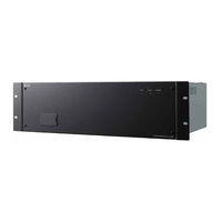
Toa RM-210 Instruction Manual (328 pages)
Integrated Voice Evacuation System
Brand: Toa
|
Category: Security System
|
Size: 6 MB
Table of Contents
Advertisement

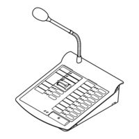
Toa RM-210 Operation Manual (149 pages)
VM-3000 Series INTEGRATED VOICE EVACUATION SYSTEM
Brand: Toa
|
Category: Security System
|
Size: 10 MB
Table of Contents
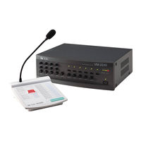
Toa RM-210 Instruction Manual (60 pages)
SYSTEM MANAGEMENT AMPLIFIER REMOTE MICROPHONE
Table of Contents
Advertisement
Toa RM-210 Instruction Manual (60 pages)
Brand: Toa
|
Category: Conference System
|
Size: 3 MB
Table of Contents
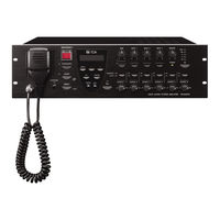
Toa RM-210 Instruction Manual (8 pages)
VM-3000 Series INTEGRATED VOICE EVACUATION SYSTEM
Brand: Toa
|
Category: Security System
|
Size: 0 MB
Table of Contents
Advertisement