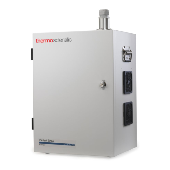
Sign In
Upload
Manuals
Brands
Thermo Scientific Manuals
Measuring Instruments
Partisol 2000i
Thermo Scientific Partisol 2000i Manuals
Manuals and User Guides for Thermo Scientific Partisol 2000i. We have
1
Thermo Scientific Partisol 2000i manual available for free PDF download: Instruction Manual
Thermo Scientific Partisol 2000i Instruction Manual (403 pages)
Air Sampler
Brand:
Thermo Scientific
| Category:
Measuring Instruments
| Size: 3.73 MB
Table of Contents
Table of Contents
13
Chapter 1 Introduction
29
Overview
29
Inlet System
31
Figure 1-1. Partisol 2000I and 2000I-D Air Sampler
31
Internal Data Storage and Data I/O
32
Programming
32
Advanced Features
32
Partisol 2000I Features
32
Partisol 2000I-D Features
34
Partisol 2000I Configuration
35
Figure 1-2. Partisol 2000I Flow Schematic
36
Partisol 2000I-D Configuration
38
Figure 1-3. Partisol 2000I-D Flow Schematic
39
Specifications
42
Table 1-1. Specifications
42
Chapter 2 Installation
43
Standard Hardware Configurations
43
Partisol 2000I
43
Partisol 2000I-D
44
Setting up the Sampler
45
Figure 2-1. Rainhood and Self Stick Gasket
45
Figure 2-2. Sampler with a Large Rainhood Installed on the Right Side Panel of the Unit and a Small Rainhood on Left
46
Figure 2-3. Sample Tube with the PM Inlet Installed
47
Figure 2-5. Ambient Temperature Probe Plugged into the "Ambient Temperature" Connector
48
Partisol Stand
49
Figure 2-6. Sampler Mounted on Optional Stand
50
Figure 2-7. Assembly Information for the Sampler Stand
50
Hardware Considerations
52
Filter Compartment Fan Operation
52
Pump Fan Operation
52
Figure 2-8. Sampler Stand Components
52
Electronics Compartment Heater Operation
53
Turning on the Partisol Sampler
53
Adjusting the Screen Contrast
53
Chapter 3 Filter Handling and Exchange
56
Pre-Sampling Filter Equilibration
56
Pre-Sampling Filter Weighing
57
Figure 3-1. Positioning a 47 MM Filter on a Balance
57
Figure 3-2. 47 MM Filter Placed in Bottom Section of Cassette. Top Part of Cassette Shown on Right
58
Figure 3-3. Filter Cassette Carrier in Transport Container for Partisol 2000I
58
Filter Exchange
59
Figure 3-4. Filter Cassette Carrier 2000I-D
59
Figure 3-5. Gripping Handle of Filter Exchange
60
Figure 3-6. Pulling Back on Handle of Filter Exchange
60
Figure 3-7. Inserting/Removing Filter Cassette in Filter Cassette Carrier in the Partisol 2000I
61
Figure 3-8. Inserting/Removing Filter Cassette in Filter Cassette Carrier in the Partisol 2000I-D
62
Post Collection Equilibration
63
Figure 3-9. Filter Cassette Separator Tool
63
Post Collection Weighing
64
Computation of Mass Concentration
65
Figure 3-10. Placing a Used 47 MM Filter on a Balance
65
Figure 4-1. PM
67
Chapter 4 Partisol 2000I Inlet Conversion
68
Partisol 2000I PM Components
68
Partisol 2000I PM WINS Components
68
Figure 4-2. Partisol 2000I Sampler with VSCC Cyclone Installed
68
Figure 4-3. WINS Impactor, Adapter, Sample Tube, and U.S. EPA PM
68
Figure 4-4. Sampler with WINS Impactor Installed
69
Figure 4-5. Straight Tube, Straight Tube Adapter, Sample Tube, and Traditional PM 10 Inlet
69
Converting a Partisol 2000I from a PM
70
Figure 4-6. Sampler with Straight Tube Installed
70
Figure 4-7. Opening the Filter Exchange Mechanism
70
Figure 4-8. Adapter for the VSCC, WINS Impactor and Straight Tube
71
Figure 4-9. Straight Tube and Adapter Installed Inside the Enclosure
71
Figure 4-10. Filter Exchange Rollers Shown on Top of Lower Guide
72
Figure 4-11. Filter Cassette Installed in the Sampler
72
Figure 4-13. Partisol 2000I PM
75
Operational Modes
77
Partisol Operational Modes
77
Stop Mode
77
Wait Mode
77
Sampling Mode
78
Done Mode
78
Error Mode
78
Audit Mode
79
Accessing the Audit Mode
79
Operation after a Power Failure
80
Sampler Settings
81
Instrument Setup
81
Default Sample Setup
82
Sample Method Definition
82
Basic Sampling Method
82
Time 2 Sampling Method
82
Advanced Filter Method
83
Default Filter Type
84
Sample Flow Rate
84
Default Sample Times
85
Start Time
85
Default Sample Duration
85
System Setup
85
Average Temp
85
Standard Temp
85
Average Pressure
85
Standard Pressure
86
Filter Fan
86
Auto Run
86
Site Identification
86
Current Date/Time
86
Sampler Operation
87
Sampler Performance Verification
87
Verifying the Ambient Air Temperature
88
Verifying the Filter Temperature
89
Figure 7-1. Filter Temperature Probe Location in Partisol 2000I
89
Figure 7-2. Filter Temperature Probe Location in Partisol 2000I-D
89
Verifying the Ambient Pressure
90
Verifying the Ambient Relative Humidity
90
External Leak Check
90
Figure 7-3. Filter Cassette and Carrier Installed into Filter Exchange Mechanism in the Partisol 2000I
91
Figure 7-4. Filter Cassettes and Carrier Installed into Filter Exchange Mechanism in the Partisol 2000I-D
91
Figure 7-5. Flow Audit Adapter Installed
92
Flow Verification
93
Figure 7-6. Streamline Pro Installed on External Sample Tube
94
Figure 7-7. Streamline Pro Installed on External Sample Tube
95
Internal Leak Check
96
Programming a Sample Run
97
Post-Sampling Verification and Data Retrieval
100
Viewing and Downloading Stored Data
101
USB Data Download
104
Data Download Via RS-232
105
Display Sampler Data
106
Identifying Sampler Status
106
Chapter 8 Calibration
107
Calibration Setup
107
Ambient Air Temperature Calibration
108
Ambient Pressure Calibration
109
Filter Pressure Calibration
109
Filter Compartment Temperature Calibration
110
Filter Temperature Calibration
110
Flow Calibration
111
Flow Calibration Setup
111
Flow Calibration - Partisol 2000I
112
Flow Calibration - Partisol 2000I-D
114
Using the Flow Calibration Cassette
116
Figure 8-1. Flow Calibrationi Cassette
116
Figure 8-2. Flow Calibration Cassette in the Front Position
117
Figure 8-3. Dual Filter Holder in the Filter Exchange
117
Figure 8-4. Filter Exchange Closed
117
Figure 8-5. Flow Calibration Cassette in the Back Position
118
Figure 8-6. Dual Filter Holder in the Filter Exchange
119
Figure 8-7. Filter Exchange Closed
119
Using the Solid Leak Check Disc
120
Figure 8-8. Solid Leak Check Disk
120
Figure 8-9. Solid Leak Check Cassette in the Front Position
120
Figure 8-10. Pull Forward on Handle of Filter Exchange
121
Figure 8-11. End of Hose Open to the Compartment Air
121
Figure 8-12. Filter Exchange Closed
122
Figure 8-13. Solid Leak Check Cassette in the Back Position
122
Figure 8-14. Pull Forward on Handle of Filter Exchange
123
Figure 8-15. End of Hose Open to the Compartment Air
123
Figure 8-16. Filter Exchange Closed
124
Chapter 9 Firmware Screen Descriptions
125
Display
125
Pushbuttons
126
Figure 9-1. Front Panel Display
126
Figure 9-2. Front Panel Pushbuttons
126
Soft Keys
127
Table 9-1. Front Panel Pushbuttons
127
Alphanumeric Entry Screen
128
Firmware Overview
128
Figure 9-3. Partisol 2000I and 2000I-D Flowchart of Menu-Driven Firmware
129
Power-Up Screen
130
Run Screen
130
Custom Run Screens
131
Main Menu
131
Sample Setup Menu
132
Apply EPA Times
132
Apply Default Times
133
Sample
133
Start
133
Stop
133
Filter Blank
134
Filter ID
135
Cassette ID
135
Filter Type
136
View Records Menu
136
Filter
137
Format of Filter Data Records
138
Interval/Srec
140
User/Lrec
140
Interval/Srec by Record Number
141
User/Lrec by Record Number
142
Interval/Srec by Date
142
User/Lrec by Date
143
Instrument Setup Menu
143
Default Sample Setup
144
Method
144
Flow Rate/Flow2 Rate
145
Filter Type/Filter2 Type
145
Default Sample Times
145
Start Time
146
Duration
146
Trigger Method
146
Setup Trigger 1-3
147
Signal
147
Minimum and Maximum Trigger
147
System Setup
148
Average Temperature
148
Standard Temperature
148
Average Pressure
149
Standard Pressure
149
Filter Fan
150
Auto Run
150
Flow Calibration Setup
151
Flow/Flow2
151
Setpoint 1-5
151
Number of Cal Points
151
Reset Flow Cal
151
FTS Constant M/B
152
Datalogging
152
Select Content
153
Fields 1-32
153
Other Measurements
154
Analog Inputs
154
Non-Measurements
154
Other Measurements 2
155
Commit Content
156
Reset to Default Content
156
Configure Datalogging
157
Logging Period Min
157
Memory Allocation Percent
157
Data Treatment
158
Flag Status Data
158
Erase User Data Log
159
Erase Interval Log
159
Site ID
159
Communications
160
Serial Settings
160
Baud Rate
161
Data Bits
161
Parity
161
Stop Bits
161
RS-232/RS-485 Selection
162
Instrument ID
163
Communication Protocol
163
Streaming Data Configuration
164
Streaming Data Interval
164
Add Labels
164
Prepend Timestamp
165
Add Flags
165
Item Number
165
Measurements
165
Other Measurements
165
Analog Inputs
165
Non-Measurements
165
Table 9-2. Data in Streaming Records - Other Measurements
167
Table 9-3. Data in Streaming Records - Analog Inputs
168
TCP/IP Settings
169
Use DHCP
169
Table 9-4. Data in Streaming Records - Non-Measurements
169
IP Address
170
Netmask
170
Default Gateway
171
Host Name
171
USB Setup
172
File Format
172
Date Format
172
Format USB Drive
172
Date/Time
173
Timezone for Timeserver
174
Password Menu
174
Set Password
175
Lock Instrument
175
Lock/Unlock and Local/Remote Operation
175
Unlock Instrument
176
Change Password
176
Remove Password
177
Restore Defaults
177
Audit and Calibration Menu
177
Audit Mode
177
Audit
178
Ambient Temperature
178
Record Reference
178
View History
178
Calibration
180
Calibrate Ambient Temperature
180
Ambient Pressure
180
Filter Temperature
181
Filter Pressure
181
Flow
182
Setpoint 1-5 for Flow
182
Slope
182
Intercept
182
Cal Setup
182
Setpoint 1-5
183
Number of Cal Points
183
Reset Flow Cal
183
Flow Constant A/B
184
Ambient RH
184
Leak Checks
185
Leak Check Internal
185
Leak Check External
185
System Status
186
Status Codes
186
Table 9-5. Status Codes
187
Alarms
188
USB Menu
189
USB Port
189
Export Data Logs
189
Export Audit History
189
Backup Configuration
192
Restore Configuration
192
Update Firmware
192
Service Menu
193
Manual Motion
193
Discrete Actions
194
Screen Contrast
194
Run Screens
195
Edit Run Screen
195
Edit Title
196
Enabled
196
Number of Items
197
Item Number
197
Other Measurements
197
Other Measurements 2
197
Analog Inputs
197
Non-Measurements
197
Table 9-6. Data in Run Screens - Other Measurements
198
Table 9-8. Data in Run Screen - Analog Inputs
200
I/O Configuration
201
Output Relay Settings
201
Logic State
202
Instrument State
202
Alarms
202
Non-Alarm
202
Digital Input Settings
204
Logic State
204
Instrument Action
204
Analog Output Configuration (Select Channel)
205
Allow Over/Under Range
205
Analog Output Configuration (Select Action)
205
Select Range
206
Choose Signal to Output
206
Table 9-9. Analog Output Zero and Full Scale Values
207
Table 9-10. Signal Types Group Choices
208
Analog Input Configuration
209
Descriptor
209
Units
210
Decimal Places
210
Number of Table Points
211
Volts
211
User Value
211
Set Serial Number
212
Options Menu
212
Enable I/O Board
213
Display Pixel Test
213
Service Mode
213
Diagnostics
214
Program Versions
214
Voltages
214
Motherboard Voltages
215
Interface Board Voltages
215
I/O Board Voltages
215
Analog Input Readings
216
Analog Input Voltages
216
Digital Inputs
216
Relay States
217
Test Analog Outputs
217
Set Analog Outputs
218
Contact Information
218
Preventive Maintenance
219
Safety Precautions
219
Routine Maintenance Items
219
Partisol 2000I Maintenance Items
220
Partisol 2000I-D Maintenance Items
220
Inlet Maintenance
220
Cleaning the PM
221
PM Inlet Removal and Disassembly
221
Top Acceleration Assembly Cleaning and Maintenance
221
Inlet
221
Lower Collector Assembly Cleaning and Maintenance
223
PM Inlet Reassembly and Reinstallation
224
Cyclone Maintenance
224
Cyclone Inlet Cleaning
225
Figure 10-2. Main Components of the Cyclone Fractionator
225
WINS PM2.5 Impactor Maintenance
227
WINS Impactor Removal
227
Figure 10-3. Cyclone Fractionator Components
227
WINS Impactor Cleaning
228
Figure 10-4. Adapter and WINS Impactor
228
Figure 10-5. Upper and Lower Sections of the Impactor Assembly (on Left and Right Sides of Figure)
228
Figure 10-6. Coating the 37 MM Glass Filter with Oil
229
WINS Impactor Reinstallation
230
Virtual Impactor Maintenance Partisol 2000I-D
230
Virtual Impactor Cleaning Partisol 2000I-D
231
Figure 10-7. the Virtual Impactor Installed
231
Figure 10-8. Drawing of Disassembled Virtual Impactor
232
V-Seals Cleaning and Replacement
233
Figure 10-9. Grasping the Handle of the Filter Exchange Mechanism
233
Figure 10-10. Pulling Backward on the Handle of the Filter Exchange Mechanism
234
Figure 10-11. Lifting the Rollers through the Guide Slots
234
Figure 10-12. Upper and Lower V-Seals on Partisol 2000I
235
Figure 10-13. Upper and Lower V-Seals on Partisol 2000I-D
235
In-Line Filters Replacement
236
Figure 10-14. V-Seal on Inlet Adapter Tube on 2000I-D
236
Service Locations
237
Chapter 11 Troubleshooting
239
Diagnostics
239
System Status
240
Alarms
240
Troubleshooting Guide
240
Table 11-1. Diagnostic Menu Selections
240
Board-Level Connection Diagram
241
Table 11-2. Troubleshooting Guide
241
Figure 11-1. Board-Level Connection Diagram 2000I
242
Figure 11-2. Board-Level Connection Diagram 2000I-D
243
Connector Pin Descriptions
244
Table 11-3. Motherboard Connector Pin Descriptions
244
Table 11-4. Backplane Board Connector Pin Descriptions
251
Table 11-5. Partisol Measurement Interface Board Connector Pin Descriptions
255
Table 11-6. I/O Expansion Board (Optional) Connector Pin Descriptions
259
Service Locations
260
Chapter 12 Servicing
261
Firmware Updates
262
Parts Lists
263
Table 12-1. Partisol 2000I and 2000I-D Replacement Parts
263
Internal Cables
267
Table 12-2. Partisol 2000I and 2000I-D Internal Cables
267
External Device Connection Components
268
Table 12-3. External Device Connection Components
268
Terminal Block and Cable Kits
269
External Cables
269
Table 12-4. External Cables
269
Filter Log
270
Table 12-5. Color Codes for 25-Pin and 37-Pin Cables
270
Service Locations
272
Chapter 13 Electronics and I/O Components
273
Electronics
273
Motherboard
273
I/O Expansion Board
274
Digital Output Board
274
I/O Components
274
Analog Voltage Outputs
275
Analog Current Outputs (Optional)
275
Analog Voltage Inputs (Optional)
275
Digital Relay Outputs
276
Digital Inputs
276
Serial Ports
276
RS-232 Connection
276
Ethernet Connection
277
Table 13-1. RS-232 DB9 Connector Pin Configuration
277
Table 13-2. RS-485 DB9 Connector Pin Configuration
277
External Accessory Connector
278
USB Port
278
Appendix A Warranty
279
Appendix B C-Link Protocol Commands
281
Instrument Identification Number
281
Commands
282
Commands List
283
Table B-1. C-Link Protocol Commands
283
Measurements
287
Figure B-1. Flags
287
Diagnostics
290
Datalogging
291
Table B-2. Record Output Formats
294
Table B-3. Stream Time Values
297
Keys/Display
299
Hardware Configuration
300
Table B-4. Contrast Levels
300
Communications Configuration
302
Table B-5. Reply Termination Formats
305
Table B-6. Allow Mode Command Values
307
Table B-7. Power up Mode Values
308
I/O Configuration
309
Table B-8. Set Layout Ack Values
309
Table B-9. Analog Current Output Range Values
310
Table B-10. Analog Voltage Output Range Values
310
Table B-11. Default Output Assignment
312
Record Layout Definition
315
Format Specifier for Binary Responses
315
Format Specifier for Front-Panel Layout
316
Text
316
Value String
316
Value Source
316
Alarm Information
317
Translation Table
317
Selection Table
317
Button Designator
317
Examples
318
Appendix Cmodbus Protocol
321
Serial Communication Parameters
321
TCP Communication Parameters
322
Application Data Unit Definition
322
Slave Address
322
MBAP Header
322
Function Code
322
Data
322
Error Check
323
Function Codes
323
(0X01/0X02) Read Coils / Read Inputs
323
(0X03/0X04) Read Holding Registers / Read Input Registers
325
(0X05) Force (Write) Single Coil
327
MODBUS Addresses Supported
328
Table C-1. Read Coils for 2000I and 2000I-D
329
Table C-2. Read Registers for 2000I and 2000I-D
329
Table C-3. Write Coils for 2000I and 2000I-D
331
Appendix D Communications Using Iport or Rpcomm
333
Iport
333
Rpcomm
333
Installing Rpcomm
334
Obtaining Rpcomm Installation Files
334
Installing Rpcomm Onto a Computer
334
Updating the List of Program Register Codes in Rpcomm
335
Instrument Setup for Direct Communication Using Rpcomm
336
Using Rpcomm
336
Figure D-1. Connector Panel
336
Executing Rpcomm
337
Figure D-2. Serial Setup Screen
337
Figure D-3. Executing Rpcomm
338
Figure D-4. Connect List Screen
338
Creating a New Connection
339
Figure D-5. Connection Type Screen
339
Figure D-6. AK Protocol Setup Screen
340
Figure D-7. Communication Port Setup Screen
341
Figure D-8. Save Connection Group Screen
342
Figure D-9. Main Screen
342
Downloading Stored Data
343
Setting the Storage Pointer Positions
343
Figure D-10. Storage Pointer Screen
343
Downloading Data
344
Figure D-11. Control Buttons on the Storage Pointer Screen
344
Figure D-12. Download Data Screen
345
Figure D-13. Control Buttons on the Download Data Screen
345
Manipulating Downloaded Data
346
Copying Data to the Clipboard
346
Figure D-14. Downloaded Filter Data
347
Figure D-15. Downloaded Interval Data
347
Figure D-16. Downloaded Input Data
348
Scheduling Data Downloads
349
Figure D-17. Schedule Downloads Screen
349
Figure D-18. Example of a Scheduled Download from the Connect List Screen
350
Viewing System Registers
351
Prcomm Modem Communications
352
Figure D-19. Registers Screen
352
Standard Commercial External Modem Setup
353
Rpcomm Setup for Use through a Modem
354
Figure D-20. Connect List Screen
355
Figure D-21. Connection Type Screen
356
Figure D-22. AK Protocol Setup Screen
356
Figure D-23. Modem Properties Screen
357
Figure D-24. Dialing Properties Screen
358
Serial Switching Device Setup
359
Multiple Instruments of the same Model
359
Figure D-25. Main Screen
359
Multiple Instruments of Different Models
361
Connecting a Series 1400A and a Partisol 2000I-D
362
Table D-1. Communication Parameters
363
Connecting a Model 2000-FRM and a Partisol 2000I/2000I-D Sampler
368
Figure D-27. Communication Port Setup Screen
371
Appendix Eak Protocol
375
TCP Communication Parameters
375
Abbreviations Used
375
Basic Command Structure
376
Commands List
377
Table E-1. Commands List
378
Program Register Codes
387
Table E-2. Program Register Codes
387
PRC Values Defined by Codes
398
Advertisement
Advertisement
Related Products
Thermo Scientific 20 GENESYS
Thermo Scientific Sarasota 200
Thermo Scientific 20-35-NM-F
Thermo Scientific 20-54-NM-SS
Thermo Scientific 20-35-NM-DIN
Thermo Scientific 20-52-NM
Thermo Scientific 20-59-NM
Thermo Scientific 20-55-NM-P
Thermo Scientific Partisol 2000i-D
Thermo Scientific MIRAN 205B Series
Thermo Scientific Categories
Laboratory Equipment
Measuring Instruments
Accessories
Refrigerator
Freezer
More Thermo Scientific Manuals
Login
Sign In
OR
Sign in with Facebook
Sign in with Google
Upload manual
Upload from disk
Upload from URL