Sign In
Upload
Manuals
Brands
Thermal Dynamics Manuals
Welding System
ULTRA-CUT 200 XT
Thermal Dynamics ULTRA-CUT 200 XT Manuals
Manuals and User Guides for Thermal Dynamics ULTRA-CUT 200 XT. We have
1
Thermal Dynamics ULTRA-CUT 200 XT manual available for free PDF download: Operating Manual
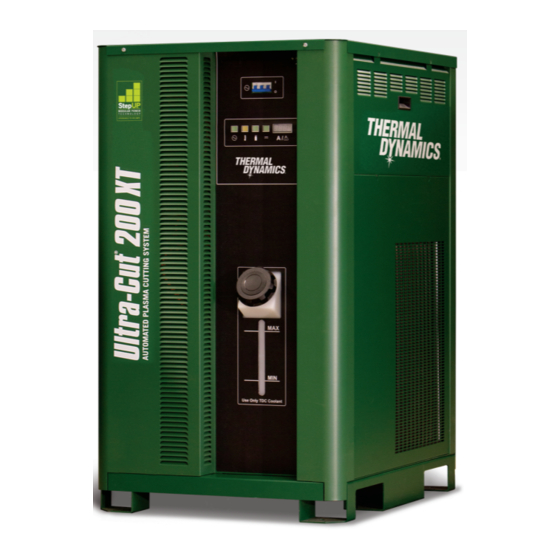
Thermal Dynamics ULTRA-CUT 200 XT Operating Manual (228 pages)
PLASMA CUTTING SYSTEM AUTOMATED GAS CONTROL
Brand:
Thermal Dynamics
| Category:
Welding System
| Size: 43.48 MB
Table of Contents
User Responsibility
4
Table of Contents
7
Section 1: Safety
11
Safety Precautions - ENGLISH
11
Précautions de Sécurité - FRENCH CANADIAN
16
Section 2: Specifications
21
General Description of the System
21
Plasma Power Supply
21
Remote Arc Starter
21
Gas Control Module
21
Precision Plasma Cutting Torch
22
Specifications & Electrical Requirements
22
Power Supply Dimensions
23
Power Supply Rear Panel Features
24
Gas Requirements
25
Gas Applications
25
XT Torch Specifications
26
Section 3: Installation
29
Installation Requirements
29
System Layout
30
Recommended Gas Supply Hose
30
Leads and Cables All Amperage
31
Lift the Power Supply
32
Connect Input Power and Ground Cables
33
Connect Work Cable and Pilot and Negative Leads
34
Ground Connections
35
Connect Coolant Leads
38
Connect Cables for CNC, Remote Arc Starter, DMC-3000 and HE 400
39
Handling and Installation of Fiber Optics
40
Correct Installation
42
Connect DMC-3000 Fiber Optic Cable to CCM
44
Set Switches on the Command - Control Module
46
Height Control Connections
48
DMC-3000 Gas Manifold Control Installation
49
DPC-3000 Gas Pressure Control Installation
52
Fiber Optic Cable Installation from CCM to DMC-3000
55
Fiber Optic Cable Installation from DMC-3000 to DPC-3000
57
Install TSC-3000 Touch Screen Control
59
Optional HE400XT COOLER
60
Install Remote Arc Starter
62
Connecting Torch
69
Install Consumable Torch Parts
71
Voltage Divider for Ihc Torch Height Control
73
Control Cable
74
Complete the Installation
75
Section 4: Operation
77
Power Supply Control Panel
77
System Operation
77
TSC-3000 Navigation Functions
79
TSC-3000 Initial Setup ONLY
80
TSC-3000 Selecting New Process
81
TSC-3000 Selecting Recently Used Process
82
TSC-3000 Creating a Custom Process
83
Back up and Restoration of Custom Processes
85
Sequence of Operation
87
Gas Selection
90
CCM Status Codes
91
DMC-3000 Status Codes
99
DPC-3000 Status Codes
101
Remote Arc Starter Trouble Shooting
104
Section 5: Maintenance
105
General Maintenance
105
External Coolant Filter Cleaning Procedure
105
Coolant Replacement Procedure
106
Section 6: Replacement Assemblies & Parts
107
Replacement Power Supply
107
System Layout
107
Recommended Gas Supply Hose
107
Leads and Cables All Amperages
108
Power Supply External Replacement Parts
110
Power Supply Replacement Parts - Upper Right Side
111
Power Supply Replacement Parts - Lower Right Side
112
Power Supply Replacement Parts - Rear Panel
113
Power Supply Replacement Parts - Left Side
114
Dfc-3000 Automated Gas Control System Replacement Components
115
DMC-3000 Gas Control Module Replacement Parts
116
DPC-3000 Gas Control Module Replacement Parts
117
TSC-3000 Touch Screen Control Remote and Internal Replacement Parts
118
Remote Arc Starter (RAS-1000) Replacement Parts
119
Optional HE400XT Heat Exchanger - Replacement Parts
120
Torch Maintenance
121
Consumable Removal
121
O-Ring Lubrication
122
Parts Wear
122
Torch Consumables Installation
123
Coolant Leak Trouble-Shooting
125
Appendix 1: Cnc - Control Module Pcb Connections
127
Appendix 2: Serial Communications
128
A2.01 Cables and Switch Settings for 2 and 4 Wire
128
Appendix 3: Cnc
130
CNC Functions
130
CNC Input / Output Descriptions
132
Simplified CNC Circuit
134
CNC Connections
136
CNC Cable Color Code
137
Appendix 4: DMC-3000 Control Pcb Layout
138
Appendix 5: Dpc-3000 Control Pcb Layout
139
Appendix 6: DMC-3000 / Dpc-3000 Power Supply Pcb Layout
140
Appendix 7: Tsc-3000 Pcb Layout
141
Appendix 8: CCM Cpu Pcb Layout
142
Appendix 9: CCM I/O Pcb Layout
144
Appendix 10: Pilot Pcb Layout
146
Appendix 11: Relay and Interface Pcb Layout
148
Appendix 12: Display Pcb Layout
150
Appendix 13: System Bias Pcb Layout
152
Appendix 14: Main Inverter Bottom Pcb Layout
154
Appendix 15: Main Inverter Top Pcb Layout
156
Appendix 16: Control and Fault Pcb Layout
158
Appendix 17: Cap Bias Bottom Pcb Layout
160
Appendix 18: Cap Bias Top Pcb Layout
161
Appendix 19: Suppressor Pcb Layout
162
Appendix 20: Cooling Diagram
163
Appendix 21: Remote Arc Starter Schematic
164
Appendix 22: Schematic, Dfc-3000 Auto Gas Box System
166
Appendix 23: System Schematic 200A, 480V
168
Appendix 24: System Schematic 200A, 480V
170
Appendix 25: Advanced Troubleshooting
172
Appendix 26: Sl100 Interconnection
216
Appendix 27: He 400 Xt Connection
218
Appendix 28: Sl100 Torch Option
219
Replacement Parts
224
Appendix 29: Publication History
226
Advertisement
Advertisement
Related Products
Thermal Dynamics Pak Master 25
Thermal Dynamics VICTOR 200 AUTO-CUT
Thermal Dynamics 200 ULTRA-CUT
Thermal Dynamics ULTRA-CUT 100
Thermal Dynamics Ultra-Cut 400
Thermal Dynamics ULTRA-CUT 400 XT
Thermal Dynamics Ultra-Cut 300 XT
Thermal Dynamics Ultra-cut 300
Thermal Dynamics Cutmaster 25mm
Thermal Dynamics 1-4200-6
Thermal Dynamics Categories
Welding System
Power Supply
Cutter
Controller
Flashlight
More Thermal Dynamics Manuals
Login
Sign In
OR
Sign in with Facebook
Sign in with Google
Upload manual
Upload from disk
Upload from URL