Sign In
Upload
Manuals
Brands
Thermal Dynamics Manuals
Welding System
ULTRA-CUT 400 XT
Thermal Dynamics ULTRA-CUT 400 XT Manuals
Manuals and User Guides for Thermal Dynamics ULTRA-CUT 400 XT. We have
1
Thermal Dynamics ULTRA-CUT 400 XT manual available for free PDF download: Operating Instructions Manual
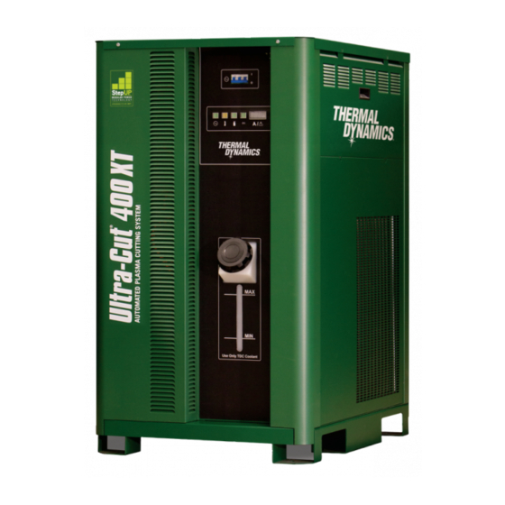
Thermal Dynamics ULTRA-CUT 400 XT Operating Instructions Manual (214 pages)
PLASMA CUTTING SYSTEM
Brand:
Thermal Dynamics
| Category:
Welding System
| Size: 26.85 MB
Table of Contents
User Responsibility
4
Table of Contents
7
Section 1: Safety
11
Safety Precautions - ENGLISH
11
Précautions de Sécurité - FRENCH CANADIAN
16
Section 2: Specifications
21
General Description of the System
21
Plasma Power Supply
21
Remote Arc Starter
21
Gas Control Module
21
Precision Plasma Cutting Torch
21
Specifications & Electrical Requirements
21
Power Supply Dimensions
22
Power Supply Rear Panel Features
23
Gas Requirements
24
Gas Applications
24
XT Torch Specifications
25
Section 3: Installation
27
Installation Requirements
27
System Layout
28
Recommended Gas Supply Hose
29
Leads and Cables All Amperage
29
Lift the Power Supply
30
Connect Input Power and Ground Cables
31
Connect Work Cable and Pilot and Negative Leads
32
Ground Connections
33
Connect Coolant Leads
36
Connect Cables for CNC, Remote Arc Starter, GCM and HE 400
37
Handling and Installation of Fiber Optics
38
Correct Installation
40
Set Switches on the Command - Control Module
41
Height Control Connections
43
Gas Control Module Installation
44
Fiber Optic Cable Installation
46
Gas Control Module: Control, Input, and Output Connections
48
He400Xt Cooler
49
Install Remote Arc Starter
51
Torch Valve Installation
58
Connecting Torch
60
Install Consumable Torch Parts
61
Voltage Divider for Ihc Torch Height Control
64
Complete the Installation
66
Section 4: Operation
67
Power Supply Control Panel
67
System Operation
68
Gas Selection
70
GCM 2010 Gas Control Module Operation
72
GCM 2010 First Time Operation Matching Gas Control to Lead Length
76
GCM 2010 Sequence of Operation
76
Power Supply Status Codes
79
Remote Arc Starter Trouble Shooting
87
Section 5: Maintenance
89
General Maintenance
89
External Coolant Filter Cleaning Procedure
89
Coolant Replacement Procedure
90
Section 6: Replacement Assemblies & Parts
91
Replacement Power Supply
91
System Layout
92
Recommended Gas Supply Hose
92
Leads and Cables All Amperages
93
Power Supply External Replacement Parts
95
Power Supply Replacement Parts - Upper Right Side
96
Power Supply Replacement Parts - Lower Right Side
97
Power Supply Replacement Parts - Rear Panel
98
Power Supply Replacement Parts - Left Side
99
Gas Control Module (GCM-2010) Replacement Parts
100
Gas Control Module (GCM-2010) Replacement Parts
101
Remote Arc Starter (RAS-1000 XT) Replacement Parts
102
HE400XT Heat Exchanger - Replacement Parts
103
XTL Torch Valve Assembly External Replacement Parts
104
XTL Torch Valve Assembly Internal Replacement Parts
105
Torch Maintenance
107
Consumable Removal
107
Section 7: Torch Maintenance
107
O-Ring Lubrication
108
Parts Wear
109
Torch Consumables Installation
110
Coolant Leak Trouble-Shooting
112
APPENDIX 1: Remote Arc Starter Schematic
115
APPENDIX 2: Gas Control and Torch Valve Schematic
116
APPENDIX 3: Gas Control Module Plumbing Diagram
118
APPENDIX 4: Gas Control Module PCB Layout
119
APPENDIX 5: Gas Control Display Module PCB Layout
120
APPENDIX 6: CNC - Control Module PCB Connections
121
Appendix 7: Cnc
122
CNC Functions
122
CNC Input / Output Descriptions
124
Simplified CNC Circuit
126
CNC Connections
128
CNC Cable Color Code
129
APPENDIX 8: CCM CPU PCB Layout
130
APPENDIX 9: CCM I/O PCB Layout
132
APPENDIX 10: Pilot PCB Layout
134
APPENDIX 11: Relay and Interface PCB Layout
136
APPENDIX 12: Display PCB Layout
138
APPENDIX 13: System Bias PCB Layout
140
APPENDIX 14: Main Inverter Bottom PCB Layout
142
APPENDIX 15: Main Inverter Top PCB Layout
144
APPENDIX 16: Control and Fault PCB Layout
146
APPENDIX 17: Cap Bias Bottom PCB Layout
148
APPENDIX 18: Cap Bias Top PCB Layout
149
APPENDIX 19: Suppressor PCB Layout
150
Appendix 20: Cooling Diagram
151
APPENDIX 21: System Schematic 400A, 480V
152
APPENDIX 22: System Schematic 400A, 480V
154
Appendix 23: Advanced Troubleshooting
156
Appendix 24: Sl100 Interconnection
202
Appendix 25: He 400 Xt Connection
204
APPENDIX 26: SL100 Torch Option
205
Replacement Parts
210
Appendix 27: Publication History
212
Advertisement
Advertisement
Related Products
Thermal Dynamics 42 CUTMASTER
Thermal Dynamics Ultra-Cut 400
Thermal Dynamics CutMaster 40MM
Thermal Dynamics ULTRA-CUT 100
Thermal Dynamics ULTRA-CUT 200 XT
Thermal Dynamics Ultra-Cut 300 XT
Thermal Dynamics Ultra-cut 300
Thermal Dynamics 1-4200-6
Thermal Dynamics 1-4730-6
Thermal Dynamics 101 CUTMASTER
Thermal Dynamics Categories
Welding System
Power Supply
Cutter
Controller
Flashlight
More Thermal Dynamics Manuals
Login
Sign In
OR
Sign in with Facebook
Sign in with Google
Upload manual
Upload from disk
Upload from URL