Sign In
Upload
Manuals
Brands
Thermal Dynamics Manuals
Welding System
200 ULTRA-CUT
User Manuals: Thermal Dynamics 200 ULTRA-CUT System
Manuals and User Guides for Thermal Dynamics 200 ULTRA-CUT System. We have
1
Thermal Dynamics 200 ULTRA-CUT System manual available for free PDF download: Operating Manual
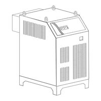
Thermal Dynamics 200 ULTRA-CUT Operating Manual (156 pages)
PLASMA CUTTING SYSTEM
Brand:
Thermal Dynamics
| Category:
Welding System
| Size: 15 MB
Table of Contents
Table of Contents
5
General Information
9
Notes, Cautions and Warnings
9
Important Safety Precautions
9
Publications
11
Declaration of Conformity
13
Statement of Warranty
14
Section 2: Specifications
15
General Description of the System
15
Plasma Power Supply
15
Remote Arc Starter
15
Gas Control Module
15
Precision Plasma Cutting Torch
15
Specifications & Electrical Requirements
16
System Component Layout
16
Power Supply Dimensions
17
Power Supply Rear Panel Features
18
Gas Requirements
19
Gas Applications
19
XTTM-300 Torch Specifications
22
Section 3: Installation
23
Installation Requirements
23
System Layout
24
Cables & Leads Identification
25
Lift the Power Supply
26
Remove the Connections Cover
27
Ground Connections
32
Connect Work Cable and Pilot and Negative Leads
34
Connect Coolant Leads
35
Connect Control Cables for CNC, Remote Arc Starter, and GCM
36
Connect Fiber Optic Cable (Type 2 Internal Control Module)
37
Set Switches on the Command - Control Module (Type 2 Module)
38
Height Control Connections
40
Gas Control Module Installation
41
Fiber Optic Cable Installation
43
Gas Control Module: Control, Input, and Output Connections
45
Install Remote Arc Starter
46
Original & XTL Torch Valve Installation
55
Connecting Torch
57
Install Consumable Torch Parts
59
Complete the Installation
63
Section 4: Operation
65
Power Supply Control Panel
65
Start-Up Sequence
66
Gas Control Module Operation
67
Gas Control Module: Controls & Indicators
68
Sequence of Operation
71
Nitride Build-Up
72
Gas Selection
73
Power Supply Status Codes
74
Remote Arc Starter: Service Chart
78
Remote Arc Starter: Spark Gap Adjustment
79
Section 5: Maintenance
81
Periodic Checks
81
External Coolant Filter Cleaning Procedure
81
Internal Coolant Filter Cleaning Procedure
82
Coolant Replacement Procedure
82
Section 6: Replacement Assemblies & Parts
83
Main Component / System Replacement
83
System Layout
84
Leads and Cables
85
Recommended Gas Supply Hose
85
Power Supply External Replacement Parts
90
Power Supply Replacement Parts - Right Side
91
Power Supply Replacement Parts - Right Side
92
Power Supply Replacement Parts - Right Side
93
Power Supply Replacement Parts - Front Panel
94
Power Supply Replacement Parts - Front Panel
95
Power Supply Replacement Parts - Right Side
96
Power Supply Replacement Parts - Rear Panel
97
Power Supply Replacement Parts - Right Side
98
Power Supply Replacement Parts
99
Power Supply Replacement Parts - Right Side
100
Power Supply Replacement Parts
101
Power Supply Replacement Parts - Right Side
102
Gas Control Module (GCM-2010) Replacement Parts
103
Gas Control Module (GCM-2010) Replacement Parts
104
Remote Arc Starter (RAS-1000) Replacement Parts
105
Remote Arc Starter (RAS-1000) Replacement Parts
106
Command & Control Module Type 2 - Replacement Parts
107
XTL Torch Valve Assembly External Replacement Parts
108
XTL Torch Valve Assembly Internal Replacement Parts
109
Section 7: Torch Maintenance
111
Consumable Removal
111
O-Ring Lubrication
112
Parts Wear
112
Torch Consumables Installation
113
Coolant Leak Trouble-Shooting
115
APPENDIX 1: Remote Arc Starter Schematic
117
APPENDIX 2: Gas Control and Torch Valve Schematic
118
APPENDIX 3: Gas Control Module
120
APPENDIX 4: Gas Control Module PCB Layout
121
APPENDIX 5: Gas Control Display Interface PCB Layout
122
APPENDIX 6: CCM CPU PCB Layout
123
APPENDIX 7: CCM Input / Output PCB Layout
124
APPENDIX 8: CNC - Control Module PCB Connections
125
CNC Functions
126
CNC Input / Output Descriptions
127
Simplified CNC Circuit
128
APPENDIX 9: Schematic: 230/460V Unit W/ Chopper Pilot W/ Diode
130
APPENDIX 9: Schematic: 230/460V Unit W/ Chopper Pilot W/ Diode Continued
132
APPENDIX 10: Schematic: 230/460V Unit W/ Resistor Pilot
134
APPENDIX 10: Schematic: 230/460V Unit W/ Resistor Pilot Continued
136
APPENDIX 11: Schematic: CCC 400V Unit W/ Chopper Pilot
138
APPENDIX 11: Schematic: CCC 400V Unit W/ Chopper Pilot Continued
140
APPENDIX 12: Schematic: CE 400V Unit W/ Chopper Pilot
142
APPENDIX 12: Schematic: CE 400V Unit W/ Chopper Pilot Continued
144
APPENDIX 13: Schematic: CE 400V Unit W/ Resistor Pilot
146
APPENDIX 13: Schematic: CE 400V Unit W/ Resistor Pilot Continued
148
APPENDIX 14: Schematic: CSA 600V Unit W/ Chopper Pilot
150
APPENDIX 14: Schematic: CSA 600V Unit W/ Chopper Pilot Continued
152
Appendix 15: Publication History
154
Global Customer Service Contact Information
155
Advertisement
Advertisement
Related Products
Thermal Dynamics Pak Master 25
Thermal Dynamics ULTRA-CUT 200 XT
Thermal Dynamics VICTOR 200 AUTO-CUT
Thermal Dynamics Cutmaster 25mm
Thermal Dynamics 1-4200-6
Thermal Dynamics 1-4730-6
Thermal Dynamics 101 CUTMASTER
Thermal Dynamics 152 CUTMASTER
Thermal Dynamics 35C
Thermal Dynamics 35C DRAG-GUN PLUS
Thermal Dynamics Categories
Welding System
Power Supply
Cutter
Controller
Flashlight
More Thermal Dynamics Manuals
Login
Sign In
OR
Sign in with Facebook
Sign in with Google
Upload manual
Upload from disk
Upload from URL