Sign In
Upload
Manuals
Brands
Texas Instruments Manuals
Microcontrollers
DLP Discovery 4100
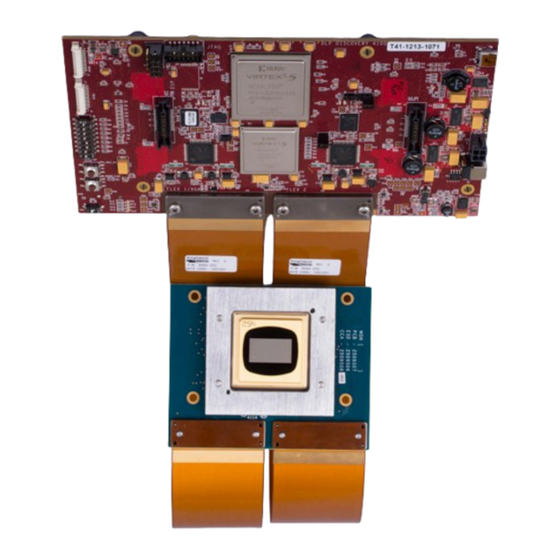
Texas Instruments DLP Discovery 4100 Manuals
Manuals and User Guides for Texas Instruments DLP Discovery 4100. We have
2
Texas Instruments DLP Discovery 4100 manuals available for free PDF download: User Manual
Texas Instruments DLP Discovery 4100 User Manual (61 pages)
Development Platform
Brand:
Texas Instruments
| Category:
Microcontrollers
| Size: 2 MB
Table of Contents
Table of Contents
1
Introduction
4
Welcome
4
Overview
5
Table 2-1. D4100 Platform Evms and DMD
5
The DLP Discovery 4100 Development Platform
6
Figure 2-1. D4100 Platform Diagram
6
DLP Discovery 4100 Development Platform Photo
8
Figure 2-2. DLPLCRC410EVM Connected to DLPLCR95EVM
8
Key Components
9
Figure 2-3. DLPLCRC410EVM Controller Board Key Components
9
Hardware Overview and Setup
12
Getting Started
12
User Connectors and I/O
12
Figure 3-1. DLPLCRC410EVM Controller Connectors (Top View)
12
Figure 3-2. DLPLCRC410EVM Controller Connectors (Bottom View)
13
Table 3-1. J12 Input Power Pinout
13
Table 3-2. J18 Input Power Pinout
13
Table 3-3. J1 USB Pinout
14
Table 3-4. J3 USB GPIO
14
Table 3-5. J6 GPIO_A Connector
14
Table 3-6. J8 DLPC410 Mictor Connector
15
Table 3-7. J9 USB/APPSFPGA Mictor Connector
16
Table 3-8. J13 DMD Flex Connector 1
18
Table 3-9. J14 DMD Flex Connector 2
20
Table 3-10. J15 DDR2 SODIMM Connector
21
Table 3-11. J16 EXP-1
22
Table 3-12. J16 EXP-1 Power and Ground
23
Table 3-13. J17 EXP-2 Connector
24
Table 3-14. J17 EXP-2 Power and Ground
25
Table 3-15. H1 Xilinx APPSFPGA JTAG Header
25
Configuration Jumpers
26
Figure 3-3. DLPLCRC410EVM Controller Configuration Jumpers
26
Table 3-16. EXP Voltage Select
26
Table 3-17. APPSFPGA Revision Select
26
Switches
27
Figure 3-4. DLPLCRC410EVM On-Board Switches
27
Table 3-18. Shared USB Signal Enable/Disable
27
Table 3-19. DLPA200 B Output Enable
27
Table 3-20. SW1 Dip Switch Assignments
28
Power and Status Leds
29
Figure 3-5. DLPLCRC410EVM Controller Board Indicators
29
Test Points
30
Figure 3-6. DLPLCRC410EVM Test Point Locations
30
Table 3-21. DLPLCRC410EVM Test Point Net Names
30
Software
31
Figure 4-1. Discovery 4100 Explorer GUI
31
Overview
32
Table 4-1. DMD Characteristics
32
DLP Discovery 4100 Operation
33
Figure 4-2. Updating Driver Software
33
Figure 4-3. Browse for Driver Software
34
Figure 4-4. Pick from a List of Device
34
Figure 4-5. Select Universal Serial Bus Devices
35
Figure 4-6. Have Disk
35
Figure 4-7. Browse for .Inf File
36
Figure 4-8. Select TI D4100 Explorer
36
Figure 4-9. Driver Installation Window
37
Figure 4-10. Verify Device
37
Figure 4-11. Discovery 4100 Explorer USB and DMD - Connection Status
38
Graphical User Interface
39
Figure 4-12. Graphical User Interface Layout
39
Figure 4-13. Menu Bar
39
Figure 4-14. File Menu
40
Figure 4-15. View Menu
40
Figure 4-16. DMD Menu
40
Figure 4-17. Execution Menu
41
Figure 4-18. Test Patterns Menu
42
Figure 4-19. Help Menu
42
Figure 4-20. Toolbar
43
Figure 4-21. Script Commands Window
44
Figure 4-22. Load Tab
45
Figure 4-23. Reset Tab
46
Figure 4-24. Clear Tab
47
Figure 4-25. Float Tab
48
Figure 4-26. Control Tab
49
Figure 4-27. Status Window
50
Figure 4-28. Script Window
50
Script and Status Operations
51
DLPC410 Control Window
53
Figure 4-29. DLPC410 Control Window
53
Test Patterns Window
54
Figure 4-30. Test Patterns Window
54
Table 4-2. SW1 Dip Switch Assignments
55
About Box
56
Links
56
Figure 4-31. about Box
56
Related Documentation
57
Appendix
58
Abbreviations and Acronyms
58
Notational Conventions
58
Revision History
60
Advertisement
Texas Instruments DLP Discovery 4100 User Manual (63 pages)
Development Platform
Brand:
Texas Instruments
| Category:
Motherboard
| Size: 3 MB
Table of Contents
Description
1
Features
1
Table of Contents
2
1 Evaluation Module Overview
4
Introduction
4
Overview
4
Table 1-1. D4100 Platform Evms and DMD
5
Figure 1-1. D4100 Platform Diagram
6
Figure 1-2. DLPLCRC410EVM Connected to DLPLCR95EVM
8
2 Hardware
9
Key Components
9
Figure 2-1. DLPLCRC410EVM Controller Board Key Components
9
Hardware Overview and Setup
11
Figure 2-2. DLPLCRC410EVM Controller Connectors (Top View)
12
Figure 2-3. DLPLCRC410EVM Controller Connectors (Bottom View)
12
Table 2-1. J12 Input Power Pinout
13
Table 2-2. J18 Input Power Pinout
13
Table 2-3. J1 USB Pinout
13
Table 2-4. J3 USB GPIO
13
Table 2-5. J6 GPIO_A Connector
14
Table 2-6. J8 DLPC410 Mictor Connector
14
Table 2-7. J9 USB/APPSFPGA Mictor Connector
15
Table 2-8. J13 DMD Flex Connector 1
17
Table 2-9. J14 DMD Flex Connector 2
19
Table 2-10. J15 DDR2 SODIMM Connector
20
Table 2-11. J16 EXP-1
21
Table 2-12. J16 EXP-1 Power and Ground
22
Table 2-13. J17 EXP-2 Connector
23
Table 2-14. J17 EXP-2 Power and Ground
24
Table 2-15. H1 Xilinx APPSFPGA JTAG Header
24
Figure 2-4. DLPLCRC410EVM Controller Configuration Jumpers
25
Table 2-16. EXP Voltage Select
25
Table 2-17. APPSFPGA Revision Select
25
Figure 2-5. DLPLCRC410EVM On-Board Switches
26
Table 2-18. Shared USB Signal Enable/Disable
26
Table 2-19. DLPA200 B Output Enable
26
Table 2-20. SW1 Dip Switch Assignments
27
Figure 2-6. DLPLCRC410EVM Controller Board Indicators
28
Figure 2-7. DLPLCRC410EVM Test Point Locations
29
Table 2-21. DLPLCRC410EVM Test Point Net Names
29
3 Software
30
Figure 3-1. Discovery 4100 Explorer GUI
30
Overview
31
Table 3-1. DMD Characteristics
31
DLP Discovery 4100 Operation
32
Figure 3-2. Updating Driver Software
32
Figure 3-3. Browse for Driver Software
33
Figure 3-4. Pick from a List of Device
33
Figure 3-5. Select Universal Serial Bus Devices
34
Figure 3-6. Have Disk
34
Figure 3-7. Browse for .Inf File
35
Figure 3-8. Select TI D4100 Explorer
35
Figure 3-9. Driver Installation Window
36
Figure 3-10. Verify Device
36
Figure 3-11. Discovery 4100 Explorer USB and DMD - Connection Status
37
Graphical User Interface
38
Figure 3-12. Graphical User Interface Layout
38
Figure 3-13. Menu Bar
38
Figure 3-14. File Menu
39
Figure 3-15. View Menu
39
Figure 3-16. DMD Menu
39
Figure 3-17. Execution Menu
40
Figure 3-18. Test Patterns Menu
41
Figure 3-19. Help Menu
41
Figure 3-20. Toolbar
42
Figure 3-21. Script Commands Window
43
Figure 3-22. Load Tab
44
Figure 3-23. Reset Tab
45
Figure 3-24. Clear Tab
46
Figure 3-25. Float Tab
47
Script and Status Operations
50
DLPC410 Control Window
52
Test Patterns Window
53
About Box
54
Links
54
Table 3-2. SW1 Dip Switch Assignments
54
4 Hardware Design Files
55
5 Additional Information
55
Trademarks
55
Abbreviations and Acronyms
56
Notational Conventions
56
6 Related Documentation
57
7 Revision History
57
Advertisement
Related Products
Texas Instruments 430BOOST-SENSE1
Texas Instruments 430BOOST-TMP006 BoosterPack
Texas Instruments 46
Texas Instruments 45
Texas Instruments 47
Texas Instruments Extensa 450 Series
Texas Instruments 4 PORTS ADSL MODEM/ROUTER
Texas Instruments Technology for Innovators 4Q 2006
Texas Instruments DLP LightCrafter 4500
Texas Instruments DLP LightCrafter Display 4710 EVM
Texas Instruments Categories
Motherboard
Control Unit
Microcontrollers
Computer Hardware
Calculator
More Texas Instruments Manuals
Login
Sign In
OR
Sign in with Facebook
Sign in with Google
Upload manual
Upload from disk
Upload from URL