Sign In
Upload
Manuals
Brands
Terex Manuals
Boom Lifts
Genie Z-34/22N
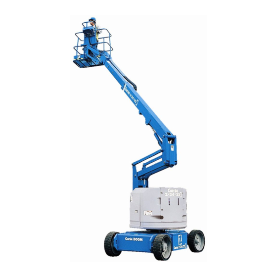
Terex Genie Z-34/22N Boom Lift Manuals
Manuals and User Guides for Terex Genie Z-34/22N Boom Lift. We have
4
Terex Genie Z-34/22N Boom Lift manuals available for free PDF download: Service Manual, Service And Repair Manual, Operator's Manual
Terex Genie Z-34/22N Service Manual (188 pages)
Brand:
Terex
| Category:
Boom Lifts
| Size: 10 MB
Table of Contents
Find a Manual for this Model
2
Serial Number Legend
5
Safety Rules
6
Table of Contents
8
Specifications
14
Machine Specifications
14
Machine Component Weights
15
Performance Specifications
16
Hydraulic Specification
17
Hydraulic Component Specifications
20
Manifold Component Specifications
20
Machine Torque Specifications
21
Hydraulic Hose and Fitting Torque Specifications
22
Torque Procedure
23
SAE and Metric Fasteners Torque Charts
25
Scheduled Maintenance Procedures
26
Introduction
26
Pre-Delivery Preparation Report
29
Maintenance Inspection Report
31
Checklist a Procedures
32
Inspect the Manuals and Decals
32
Perform Pre-Operation Inspection
33
Perform Function Tests
33
Perform 30 Day Service
34
Grease the Turntable Rotation Bearing and Worm Drive Gear
34
Replace the Drive Hub Oil
35
Checklist B Procedures
36
Inspect the Battery
36
Inspect the Electrical Wiring
37
Inspect the Tires, Wheels and Lug Nut Torque
38
Confirm the Proper Brake Configuration
39
Check the Drive Hub Oil Level and Fastener Torque
39
Test the Ground Control Override
40
Test the Platform Self-Leveling
40
Test the Drive Brakes
41
Test the Drive Speed - Stowed Position
41
Test the Drive Speed - Raised or Extended Position
42
Test the Alarm Package (if Equipped)
43
Test the Turntable Rotation Stop
44
Check the Electrical Contactors
44
Perform Hydraulic Oil Analysis
45
Test the Emergency Power System
45
Checklist C Procedures
47
Grease the Platform Overload Mechanism (if Equipped)
47
Test the Platform Overload System (if Equipped)
47
Checklist D Procedures
49
Check the Boom Wear Pads
49
Check the Free-Wheel Configuration
50
Check the Turntable Rotation Bearing Bolts
51
Replace the Drive Hub Oil
52
Replace the Hydraulic Tank Return Filter Element
52
Inspect for Turntable Bearing Wear
53
Checklist E Procedures
54
Test or Replace the Hydraulic Oil
54
Grease the Steer Axle Wheel Bearings
56
Repair Procedures
58
Introduction
58
Platform Controls
60
Controllers
60
Platform Components
62
Platform Leveling Slave Cylinder
62
Platform Rotator
63
Platform Overload System
64
Jib Boom Components
67
Platform Overload System
67
Jib Boom Bell Crank (Models Without Rotating Jib Boom)
68
Jib Boom Bell Crank (Models with Rotating Jib Boom)
69
Jib Boom Lift Cylinder
71
Primary Boom Components
72
Cable Track
72
How to Repair the Primary Boom Cable Track
72
Primary Boom
73
How to Remove the Primary Boom
73
How to Disassemble the Primary Boom
75
Primary Boom Lift Cylinder
76
Primary Boom Extension Cylinder
78
Platform Leveling Master Cylinder
80
Secondary Boom Components
81
Secondary Boom
82
Secondary Boom Lift Cylinders
87
Hydraulic Pump
90
Auxiliary and Function Pump
90
Manifolds
91
7-1 Function Manifold Components
91
Valve Adjustments - Function Manifold
95
How to Adjust the System Relief Valve
95
How to Adjust the Primary Boom down Relief Valve
95
How to Adjust the Secondary Boom down Relief Valve
96
How to Adjust the Primary Boom Extend Relief Valve
96
How to Adjust the Turntable Rotate Relief Valve
97
Jib Boom and Platform / Jib Boom Rotate Manifold Components
98
Valve Coils
100
How to Test a Coil Diode
101
Turntable Rotation Components
103
Turntable Rotation Hydraulic Motor
103
Steer Axle Components
104
Hub and Bearings
104
How to Remove the Hub and Bearings
104
How to Install the Hub and Bearings
104
Non-Steer Axle Components
106
Motor Controller
106
Fault Codes
107
Introduction
107
Fault Code Charts
109
Schematics
112
Introduction
112
Electrical Symbol Legend
113
Hydraulic Symbols Legend
114
Limit Switch Location Legend
115
Electrical Schematics - Options
116
Power Cable Wiring Diagram
117
Drive Contactor Panel Wiring Diagram
118
Manifold and Limit Switch Wiring Diagram
121
LVI/BCI Option Wiring Diagram
122
Work and Drive Lights Option
125
CTE Option, (CE Models)
126
Charger Interlock Option
129
Hydraulic Schematics
130
Hydraulic Schematic
131
Electrical Schematics - ANSI / CSA / as Models
132
Electrical Schematic, (ANSI / CSA / AS) (before Serial Numbers Z30N10-12119, Z34N10-8857 and Z3410-7774)
133
Ground Control Box Terminal Strip Wiring Diagram, (ANSI / CSA / AS) (before Serial Numbers Z3010-12119, Z34N10-8857 and Z3410-7774)
136
Ground Control Box Terminal Strip Wiring Diagram, (ANSI / CSA / AS) (before Serial Numbers Z3010-12119, Z34N10-8857 and Z3410-7774)
137
Ground Control Box Switch Panel Wiring Diagram, (ANSI / CSA / AS), (before Serial Numbers Z30N10-12119, Z34N10-8857 and Z3410-7774)
138
Platform Control Box Wiring Diagram, (ANSI / CSA / AS) (before Serial Numbers Z30N10-12119, Z34N10-8857 and Z3410-7774)
141
Electrical Schematics - CE Models
142
Electrical Schematic, (CE), (before Serial Numbers Z30N10-12119, Z34N10-8857 and Z3410-7774)
143
Ground Control Box Terminal Strip Wiring Diagram, (CE) (before Serial Numbers Z30N10-12119, Z34N10-8857 and Z3410-7774)
147
Ground Control Box Switch Panel Wiring Diagram, (CE) (before Serial Numbers Z30N10-12119, Z34N10-8857 and Z3410-7774)
148
Platform Control Box Wiring Diagram, (CE) (before Serial Numbers Z30N10-12119, Z34N10-8857 and Z3410-7774)
151
Electrical Schematics - ANSI and CSA Models
152
Electrical Schematic, (ANSI / CSA), (from Serial Numbers Z30N10-12119, Z34N10-8857 and Z3410-7774 to Z30N13-14695, Z34N13-10622 and Z3413-9441 )
153
Electrical Schematic, (ANSI / CSA)
157
Z3413-9442 to Z30N14-15221, Z34N14-10983 and Z3414-9685)
157
Ground Control Box Terminal Strip Wiring Diagram, (ANSI / CSA) (from Serial Numbers Z30N10-12119, Z34N10-8857 and Z3410-7774 to Z30N13-14695, Z34N13-10622 and Z3413-9441)
161
Ground Control Box Switch Panel Wiring Diagram, (ANSI / CSA), (from Serial Numbers Z30N10-12119, Z34N10-8857 and Z3410-7774)
162
Platform Control Box Wiring Diagram, (ANSI / CSA), (from Serial Numbers Z30N10-12119, Z34N10-8857 and Z3410-7774)
167
Z3413-9442 to Z30N14-15221, Z34N14-10983 and Z3414-9685)
168
Electrical Schematics - as / CE Models
170
Electrical Schematic, (as / CE), (from Serial Numbers Z30N10-12119, Z34N10-8857 and Z3410-7774 to Z30N13-14695, Z34N13-10622 and Z3413-9441)
171
Electrical Schematic, (as / CE)
175
Z3413-9442 to Z30N14-15221, Z34N14-10983 and Z3414-9685)
175
Ground Control Box Terminal Strip Wiring Diagram, (as / CE) (from Serial Numbers Z30N10-12119, Z34N10-8857 and Z3410-7774 to Z30N13-14695, Z34N13-10622 and Z3413-9441)
179
Ground Control Box Switch Panel Wiring Diagram, (as / CE) (from Serial Numbers Z30N10-12119, Z34N10-8857 and Z3410-7774 to Z30N13-14695, Z34N13-10622 and Z3413-9441)
181
Ground Control Box Terminal Strip Wiring Diagram, (as / CE) (from Serial Numbers Z30N13-14696, Z34N13-10623 and Z3413-9442 to Z30N14-15221, Z34N14-10983 and Z3414-9685)
183
Platform Control Box Wiring Diagram, (as / CE) (from Serial Numbers Z30N10-12119, Z34N10-8857 and Z3410-7774 to Z30N13-14695, Z34N13-10622 and Z3413-9441)
185
Platform Control Box Wiring Diagram, (as / CE)
186
Advertisement
Terex Genie Z-34/22N Service And Repair Manual (113 pages)
Brand:
Terex
| Category:
Boom Lifts
| Size: 3 MB
Table of Contents
Find a Manual for this Model
2
Revision History
3
Serial Number Legend
4
Safety Rules
5
Table of Contents
7
Specifications
11
Machine Specifications
11
Machine Component Weights
12
Performance Specifications
13
Hydraulic Oil Specifications
14
Hydraulic Component Specifications
17
Manifold Component Specifications
17
Machine Torque Specifications
18
Hydraulic Hose and Fitting Torque Specifications
19
Torque Procedure
20
Repair Procedures
22
Introduction
22
Platform Controls
24
Controllers
24
Platform Components
26
Platform Leveling Slave Cylinder
26
Platform Rotator
27
Platform Overload System
28
Jib Boom Components
31
Platform Overload System
31
Jib Boom Bell Crank (Models Without Rotating Jib Boom)
32
Jib Boom Bell Crank (Models with Rotating Jib Boom)
33
Jib Boom Lift Cylinder
35
Primary Boom Components
36
Cable Track
36
How to Repair the Primary Boom Cable Track
36
Primary Boom
37
How to Remove the Primary Boom
37
How to Disassemble the Primary Boom
39
Primary Boom Lift Cylinder
40
Primary Boom Extension Cylinder
42
Platform Leveling Master Cylinder
44
Secondary Boom Components
45
Secondary Boom
46
Secondary Boom Lift Cylinders
51
Hydraulic Pump
53
Auxiliary and Function Pump
53
Manifolds
54
7-1 Function Manifold Components
54
Valve Adjustments - Function Manifold
58
How to Adjust the System Relief Valve
58
How to Adjust the Primary Boom down Relief Valve
58
How to Adjust the Secondary Boom down Relief Valve
59
How to Adjust the Primary Boom Extend Relief Valve
59
How to Adjust the Turntable Rotate Relief Valve
60
Valve Coils
62
How to Test a Coil Diode
63
Turntable Rotation Components
64
Turntable Rotation Hydraulic Motor
64
Steer Axle Components
65
Hub and Bearings
65
How to Remove the Hub and Bearings
65
How to Install the Hub and Bearings
65
Non-Steer Axle Components
67
Motor Controller
67
Fault Codes
68
Introduction
68
Fault Code Charts
70
Schematics
73
Introduction
73
Electrical Symbol Legend
74
Hydraulic Symbols Legend
75
Limit Switch Location Legend
76
Electrical Schematics - Options
77
Power Cable Wiring Diagram
78
Drive Contactor Panel Wiring Diagram
79
Manifold and Limit Switch Wiring Diagram
82
LVI/BCI Option Wiring Diagram
83
Charger Interlock Option
86
CTE Option, (CE Models)
87
Contact Alarm Option
90
Electrical Schematics - ANSI / CSA Models
91
Electrical Schematic [ANSI / CSA]
92
Electrical Schematic [ANSI / CSA]
93
Ground Control Box Terminal Strip Wiring Diagram [ANSI / CSA]
96
Ground Control Box Switch Panel Wiring Diagram [ANSI / CSA]
97
Platform Control Box Wiring Diagram [ANSI / CSA]
100
Electrical Schematics - CE / as Models
101
Electrical Schematic [CE / AS]
102
Electrical Schematic [CE / AS]
103
Ground Control Box Terminal Strip Wiring Diagram [CE / AS]
106
Ground Control Box Switch Panel Wiring Diagram [CE / AS]
107
Platform Control Box Wiring Diagram [CE / AS]
110
Hydraulic Schematics
111
Hydraulic Schematic
112
Terex Genie Z-34/22N Operator's Manual (54 pages)
Brand:
Terex
| Category:
Boom Lifts
| Size: 1 MB
Table of Contents
Table of Contents
2
About this Manual
3
Product Identification
3
Introduction
3
Bulletin Distribution and Compliance
5
Hazard Classification
6
Symbol and Hazard Pictorials Definitions
7
General Safety
10
Personal Safety
12
Electrocution Hazards
13
Work Area Safety
13
Tip-Over Hazards
13
Collision Hazards
17
Explosion and Fire Hazards
18
Battery Safety
19
Legend
21
Controls
22
Ground Control Panel
22
Platform Control Panel
23
Inspections
24
Pre-Operation Inspection
25
Operating Instructions
37
Emergency Stop
38
Auxiliary Power
38
Drive Enable
41
Maintenance-Free Batteries
44
Observe and Obey
45
Transport and Lifting Instructions
45
Maintenance
49
Check the Hydraulic Oil Level
49
Check the Batteries
50
Scheduled Maintenance
50
Specifications
51
Advertisement
Terex Genie Z-34/22N Operator's Manual (56 pages)
Brand:
Terex
| Category:
Boom Lifts
| Size: 2 MB
Table of Contents
Table of Contents
2
Introduction
3
Symbol and Hazard Pictorials Definitions
8
General Safety
10
Personal Safety
12
Work Area Safety
13
Legend
21
Controls
22
Inspections
24
Operating Instructions
38
Transport and Lifting Instructions
46
Maintenance
50
Specifications
52
Contents of EC Declaration of Conformity
55
Advertisement
Related Products
Terex Genie Z-34/22 IC
Terex Genie Z-34/22 DC
Terex Genie Z-34/22 N
Terex Genie Z-34/22 BE
Terex Genie Z-34/22DC
Terex Genie Z-34/22
Terex Genie Z-34N
Terex Z34ND-1900
Terex Genie Z-34 DC
Terex Z34NF-17000
Terex Categories
Boom Lifts
Lifting Systems
Construction Equipment
Scissor Lifts
Forklifts
More Terex Manuals
Login
Sign In
OR
Sign in with Facebook
Sign in with Google
Upload manual
Upload from disk
Upload from URL