Sign In
Upload
Manuals
Brands
Terex Manuals
Boom Lifts
Genie S-80
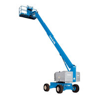
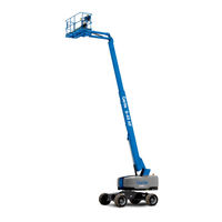
Terex Genie S-80 Manuals
Manuals and User Guides for Terex Genie S-80. We have
7
Terex Genie S-80 manuals available for free PDF download: Service And Repair Manual, Maintenance Manual, Replacement Instructions Manual, Operator's Manual
Terex Genie S-80 Service And Repair Manual (301 pages)
Brand:
Terex
| Category:
Boom Lifts
| Size: 29 MB
Table of Contents
Introduction
2
Find a Manual for this Model
2
Serial Number Legend
4
Safety Rules
5
Table of Contents
7
Specifications
15
Machine Specifications
15
Performance Specifications
16
Hydraulic Oil Specifications
16
Hydraulic Component Specifications
19
Manifold Component Specifications
20
Continental TME27 Engine Specifications
21
Deutz Td2011L04I Engine Specifications
22
Deutz TD 2.9 Engine Specifications
23
Machine Torque Specifications
26
Hydraulic Hose and Fitting Torque Specifications
27
Torque Procedure
28
Repair Procedures
30
Platform Controls
32
ALC-500 Circuit Board
32
How to Remove the ALC-500 Circuit Board
32
Joysticks
33
How to Adjust the Joystick Max-Out Setting
33
How to Adjust the Joystick Ramp Rate Setting
34
How to Adjust the Joystick Threshold Setting
36
How to Calibrate the Boom Angle Sensor
37
Platform Components
38
Platform
38
How to Remove the Platform Leveling Slave Cylinder
39
How to Bleed the Slave Cylinder
39
Platform Rotator
40
How to Remove the Platform Rotator
40
How to Bleed the Platform Rotator
41
Platform Overload System
42
Jib Boom Components
45
Jib Boom
45
Jib Boom Lift Cylinder
46
Boom Components
47
Cable Track
47
How to Remove the Cable Track, S-80
47
How to Repair the Cable Track
49
Boom
49
How to Shim the Boom
49
How to Remove the Boom
50
Boom Lift Cylinder
52
Boom Extension Cylinder
54
Boom Extend/Retract Cables
56
How to Adjust the Extend/Retract Cables
56
How to Replace the Boom Extend/Retract Cables
58
Platform Leveling Master Cylinder
60
Primary Boom Angle Sensor, S-80X
61
Engines
63
RPM Adjustment
63
Flex Plate
63
How to Remove the Flex Plate
63
How to Install the Flex Plate
66
How to Install the Pump and Bell Housing Assembly
67
Ground Controls
68
Control Relays
68
Hydraulic Pumps
69
Function Pump
69
Drive Pump
70
How to Prime the Drive Pump
71
Manifolds
72
Function Manifold
74
Valve Adjustments - Function Manifold
74
How to Adjust the System Relief Valve
74
How to Adjust the Boom down Relief Valve
74
How to Adjust the Boom Extend Relief Valve
75
Brake/Two-Speed Manifold Components
76
Turntable Rotation Manifold Components
77
Platform Rotate Manifold Components
78
Platform Manifold Components, S-80
79
Platform Manifold Components, S-85
80
Valve Adjustments - Traction Manifold
85
Valve Coils
86
Valve Coil Resistance Specifications
86
Fuel and Hydraulic Tanks
88
Fuel Tank
88
Hydraulic Tank
89
Turntable Rotation Components
91
Turntable Rotation Drive Hub Assembly
91
How to Remove the Turntable Rotation Drive Hub Assembly
91
How to Remove the Turntable Rotation Hydraulic Motor
92
How to Adjust the Turntable Rotation Gear Backlash
93
Steer Axle Components
95
Yoke and Drive Hub
95
Drive Motors
96
Drive Hubs
96
Steer Cylinders
97
Non-Steer Axle Components
98
Drive Motor
98
Drive Hub
98
Oscillating Axle Components
99
Oscillate Axle Cylinders
99
Oscillate Directional Valve
100
How to Adjust the Oscillate Relief Valve
100
How to Set up the Directional Valve Linkage
101
Fault Codes
103
Control System Fault Codes
104
How to Retrieve Control System Fault Codes
104
Control System Fault Codes
105
Fault Code Display - Deutz and Perkins Models
108
How to Retrieve Active Engine Fault Codes Deutz D 2.9 L4 and Perkins 404F-22 Models
108
22 Models
108
Soft Key Functions and Icons - Deutz D 2.9 L4 and Perkins 404F-22 Models
110
Main Menu Structure - Deutz D 2.9 L4 Models
111
Main Menu Structure - Perkins 404F-22 Models
112
Deutz D 2.9 L4 Engine Fault Codes
113
Perkins 404F-22 Engine Fault Codes
124
Continental TME27 Engine Fault Codes
126
How to Clear Engine Fault Codes from the ECM
126
Continental TME27 Engine Fault Codes
127
Schematics
132
Electrical Symbol Legend
133
Hydraulic Symbols Legend
134
Relay and Fuse Panel Legend - Deutz Td2011L04I
135
Relay and Fuse Panel Legend - Perkins 804D-33
136
Connector Pin Legends
137
Continental TME27 Engine Harness
141
S-80X Ground Control Box Wiring Diagram
143
Deutz TD2.9 L4 Engine Harness
145
Perkins 404F-22T Engine Harness
147
Electrical Schematic, S-80X - Deutz TD2.9 L4 Models (ANSI / CSA)
149
Ground Control Box, S-80X - Deutz TD2.9 L4 Models (ANSI / CSA)
153
Platform Control Box, S-80X Deutz TD2.9 L4 Models (ANSI / CSA)
155
Electrical Schematic, S-80X - Deutz Td2011L04I Models (ANSI / CSA)
157
Ground Control Box, S-80X - Deutz Td2011L04I Models (ANSI / CSA)
161
Platform Control Box, S-80X Deutz Td2011L04I Models (ANSI / CSA)
163
Electrical Schematic, S-80X - Perkins 404F-22T Models (ANSI / CSA)
165
Ground Control Box, S-80X - Perkins 404F-22T Models (ANSI / CSA)
169
Platform Control Box, S-80X Perkins 404F-22T Models (ANSI / CSA)
171
Electrical Schematic, S-80X - Perkins 804D-33 Models (ANSI / CSA)
173
Ground Control Box, S-80X - Perkins 804D-33 Models (ANSI / CSA)
177
Platform Control Box, S-80X Perkins 804D-33 Models (ANSI / CSA)
179
Electrical Schematic, S-80X - Continental TME27 Models (ANSI / CSA)
181
Ground Control Box, S-80X - Continental TME27 Models (ANSI / CSA)
185
Platform Control Box, S-80X Continental TME27 Models (ANSI / CSA)
187
Electrical Schematics, S-80X - ANSI and CSA Models
149
Electrical Schematics, S-80, S-85 - ANSI and CSA Models
189
Electrical Schematic, S-80 • S-85 - Deutz TD2.9 L4 Models (ANSI / CSA)
189
Ground Control Box, S-80 • S-85 - Deutz TD2.9 L4 Models (ANSI / CSA)
193
Platform Control Box, S-80 • S-85 - Deutz TD2.9 L4 Models (ANSI / CSA)
196
Electrical Schematic, S-80 • S-85 - Deutz Td2011L04I Models (ANSI / CSA)
197
Ground Control Box, S-80 • S-85 - Deutz Td2011L04I Models (ANSI / CSA)
201
Platform Control Box, S-80 • S-85 - Deutz Td2011L04I Models (ANSI / CSA)
204
Electrical Schematic, S-80 • S-85 - Perkins 404F-22T Models (ANSI / CSA)
205
Ground Control Box, S-80 • S-85 - Perkins 404F-22T Models (ANSI / CSA)
209
Electrical Schematic, S-80 • S-85 - Perkins 804D-33 Models (ANSI / CSA)
213
Ground Control Box, S-80 • S-85 - Perkins 804D-33 Models (ANSI / CSA)
217
Platform Control Box, S-80 • S-85 - Perkins 804D-33 Models (ANSI / CSA)205
220
Electrical Schematic, S-80 • S-85 - Continental TME27 Models (ANSI / CSA)
221
Ground Control Box, S-80 • S-85 - Continental TME27 Models (ANSI / CSA)
225
Platform Control Box, S-80 • S-85 - Continental TME27 Models (ANSI / CSA)
228
Electrical Schematics, S-80, S-85 - CE Models
229
Electrical Schematic, S-80 • S-85 - Deutz TD2.9 L4 Models (CE)
229
Ground Control Box, S-80 • S-85 Deutz TD2.9 L4 Models (CE)
234
Platform Control Box, S-80 • S-85 - Deutz TD2.9 L4 Models (CE)
236
Electrical Schematic, S-80 • S-85 - Deutz Td2011L04I Models (CE)
237
Ground Control Box, S-80 • S-85 - Deutz Td2011L04I Models (CE)
241
Platform Control Box, S-80 • S-85 - Deutz Td2011L04I Models (CE)
244
Electrical Schematic, S-80 • S-85 - Perkins 804D-33 Models (CE)
245
Ground Control Box, S-80 • S-85 - Perkins 804D-33 Models (CE)
249
Platform Control Box, S-80 • S-85 - Perkins 804D-33 Models (CE)
252
Electrical Schematic, S-80 • S-85 - Continental TME27 Models (CE)
253
Ground Control Box, S-80 • S-85 - Continental TME27 Models (CE)
257
Platform Control Box, S-80 • S-85 - Continental TME27 Models (CE)
260
Electrical Schematics, S-80, S-85 - as Models
261
Electrical Schematic, S-80 • S-85 - Deutz Td2011L04I Models (AS)
261
Ground Control Box, S-80 • S-85 - Deutz Td2011L04I Models (AS)
265
Platform Control Box, S-80 • S-85 - Deutz Td2011L04I Models (AS)
268
Electrical Schematic, S-80 • S-85 - Perkins 804D-33 Models (AS)
269
Ground Control Box, S-80 • S-85 - Perkins 804D-33 Models (AS)
273
Platform Control Box, S-80 • S-85 - Perkins 804D-33 Models (AS)
276
Electrical Schematic, S-80 • S-85 - Continental TME27 Models (AS)
277
Ground Control Box, S-80 • S-85 - Continental TME27 Models (AS)
281
Platform Control Box, S-80 • S-85 - Continental TME27 Models (AS)
284
Schematics - Options
285
Continental Options Schematic
285
Deutz and Perkins Options Schematic
287
Platform Level Cutout, CTE Option
289
12 Kw Hydraulic Generator Wiring Diagram
291
12 Kw Hydraulic Generator Electrical Schematic
293
Belt Driven Generator Option
295
Hydraulic Schematics
297
Hydraulic Schematic, 2WD Models
297
Hydraulic Schematic, 4WD Models
299
Advertisement
Terex Genie S-80 Service And Repair Manual (277 pages)
Brand:
Terex
| Category:
Boom Lifts
| Size: 25 MB
Table of Contents
Find a Manual for this Model
2
Serial Number Legend
4
Safety Rules
5
Table of Contents
7
Specifications
15
Machine Specifications
15
Performance Specifications
16
Hydraulic Oil Specifications
16
Hydraulic Component Specifications
19
Manifold Component Specifications
20
Deutz Td2011L04I Engine Specifications
21
Deutz TD 2.9 Engine Specifications
22
Machine Torque Specifications
25
Hydraulic Hose and Fitting Torque Specifications
26
Torque Procedure
27
Repair Procedures
29
Platform Controls
31
ALC-500 Circuit Board
31
How to Remove the ALC-500 Circuit Board
31
Joysticks
32
How to Adjust the Joystick Max-Out Setting
32
How to Adjust the Joystick Ramp Rate Setting
33
How to Adjust the Joystick Threshold Setting
35
How to Calibrate the Boom Angle Sensor
36
Platform Components
37
Platform
37
How to Remove the Platform Leveling Slave Cylinder
38
How to Bleed the Slave Cylinder
38
Platform Rotator
39
How to Remove the Platform Rotator
39
How to Bleed the Platform Rotator
40
Platform Overload System
41
Jib Boom Components
44
Jib Boom
44
Jib Boom Lift Cylinder
45
Boom Components
46
Cable Track
46
How to Remove the Cable Track, S-80
46
How to Repair the Cable Track
48
Boom
48
How to Shim the Boom
48
How to Remove the Boom
49
Boom Lift Cylinder
51
Boom Extension Cylinder
53
Boom Extend/Retract Cables
55
How to Adjust the Extend/Retract Cables
55
How to Replace the Boom Extend/Retract Cables
57
Platform Leveling Master Cylinder
59
Primary Boom Angle Sensor, S-80X
60
Engines
62
RPM Adjustment
62
Flex Plate
62
How to Remove the Flex Plate
62
How to Install the Flex Plate
65
How to Install the Pump and Bell Housing Assembly
66
Ground Controls
67
Control Relays
67
Hydraulic Pumps
68
Function Pump
68
Drive Pump
69
How to Prime the Drive Pump
70
Manifolds
72
Function Manifold
74
Valve Adjustments - Function Manifold
74
How to Adjust the System Relief Valve
74
How to Adjust the Boom down Relief Valve
74
How to Adjust the Boom Extend Relief Valve
75
Brake/Two-Speed Manifold Components
76
Turntable Rotation Manifold Components
77
Platform Rotate Manifold Components
78
Platform Manifold Components, S-80
79
Platform Manifold Components, S-85
80
Valve Adjustments - Traction Manifold
85
Valve Coils
86
Valve Coil Resistance Specifications
86
Fuel and Hydraulic Tanks
88
Fuel Tank
88
Hydraulic Tank
89
Turntable Rotation Components
91
Turntable Rotation Drive Hub Assembly
91
How to Remove the Turntable Rotation Drive Hub Assembly
91
How to Remove the Turntable Rotation Hydraulic Motor
92
How to Adjust the Turntable Rotation Gear Backlash
93
Steer Axle Components
95
Yoke and Drive Hub
95
Drive Motors
96
Drive Hubs
96
Steer Cylinders
97
Non-Steer Axle Components
98
Drive Motor
98
Drive Hub
98
Oscillating Axle Components
99
Oscillate Axle Cylinders
99
Oscillate Directional Valve
100
How to Adjust the Oscillate Relief Valve
100
How to Set up the Directional Valve Linkage
101
Fault Codes
103
Control System Fault Codes
104
How to Retrieve Control System Fault Codes
104
Control System Fault Codes
105
Fault Code Display - Deutz and Perkins Models
108
How to Retrieve Active Engine Fault Codes Deutz D 2.9 L4 and Perkins 404F-22 Models
108
22 Models
108
Soft Key Functions and Icons - Deutz D 2.9 L4 and Perkins 404F-22 Models
110
Main Menu Structure - Deutz D 2.9 L4 Models
111
Main Menu Structure - Perkins 404F-22 Models
112
Deutz D 2.9 L4 Engine Fault Codes
113
Perkins 404F-22 Engine Fault Codes
124
Schematics
126
Electrical Symbol Legend
127
Hydraulic Symbols Legend
128
Relay and Fuse Panel Legend - Deutz Td2011L04I
129
Engine Relay Layout - Perkins 404D-22T
130
Relay and Fuse Panel Legend - Perkins 804D-33
131
Engine Relay Layout - GM 3.0L
132
Connector Pin Legends
133
S-80X Ground Control Box Wiring Diagram
137
Deutz TD2.9 L4 Engine Harness
139
Electrical Schematic, S-80X - Deutz TD2.9 L4 Models (ANSI / CSA)
141
Ground Control Box, S-80X - Deutz TD2.9 L4 Models (ANSI / CSA)
145
Platform Control Box, S-80X Deutz TD2.9 L4 Models (ANSI / CSA)
147
Electrical Schematic, S-80X - Deutz Td2011L04I Models (ANSI / CSA)
149
Ground Control Box, S-80X - Deutz Td2011L04I Models (ANSI / CSA)
153
Platform Control Box, S-80X Deutz Td2011L04I Models (ANSI / CSA)
155
Ground Control Box, S-80X - Perkins 404D-22T Models (ANSI / CSA)
161
Platform Control Box, S-80X - Perkins 404D-22T Models (ANSI / CSA)
163
Electrical Schematic, S-80X - GM 3.0L Models (ANSI / CSA)
165
Ground Control Box, S-80X - GM 3.0L Models (ANSI / CSA)
169
Platform Control Box, S-80X GM 3.0L Models (ANSI / CSA)
171
Electrical Schematics, S-80X - ANSI and CSA Models
141
Electrical Schematics, S-80, S-85 - ANSI and CSA Models
173
Electrical Schematic, S-80 • S-85 - Deutz TD2.9 L4 Models (ANSI / CSA)
173
Ground Control Box, S-80 • S-85 - Deutz TD2.9 L4 Models (ANSI / CSA)
177
Platform Control Box, S-80 • S-85 - Deutz TD2.9 L4 Models (ANSI / CSA)
180
Electrical Schematic, S-80 • S-85 - Deutz Td2011L04I Models (ANSI / CSA)
181
Ground Control Box, S-80 • S-85 - Deutz Td2011L04I Models (ANSI / CSA)
185
Platform Control Box, S-80 • S-85 - Deutz Td2011L04I Models (ANSI / CSA)
188
Electrical Schematic, S-80 • S-85 - Perkins 404D-22T Models (ANSI / CSA)
189
Electrical Schematic, S-80 • S-85 - GM 3.0L Models (ANSI / CSA)
197
Ground Control Box, S-80 • S-85 - GM 3.0L Models (ANSI / CSA)
201
Platform Control Box, S-80 • S-85 - GM 3.0L Models (ANSI / CSA)
204
Electrical Schematics, S-80, S-85 - CE Models
205
Electrical Schematic, S-80 • S-85 - Deutz TD2.9 L4 Models (CE)
205
Electrical Schematic, S-80 • S-85 - Deutz Td2011L04I Models (CE)
206
Ground Control Box, S-80 • S-85 - Deutz Td2011L04I Models (CE)
209
Platform Control Box, S-80 • S-85 - Deutz Td2011L04I Models (CE)
212
Electrical Schematic, S-80 • S-85 - Perkins 404TD-22 Models (CE)
221
Ground Control Box, S-80 • S-85 - Perkins 404TD-22 Models (CE)
225
Platform Control Box, S-80 • S-85 - Perkins 404TD-22 Models (CE)
228
Electrical Schematic, S-80 • S-85 - GM 3.0L Models (CE)
229
Ground Control Box, S-80 • S-85 - GM 3.0L Models (CE)
233
Platform Control Box, S-80 • S-85 - GM 3.0L Models (CE)
236
Electrical Schematics, S-80, S-85 - as Models
237
Electrical Schematic, S-80 • S-85 - Deutz Td2011L04I Models (AS)
237
Ground Control Box, S-80 • S-85 - Deutz Td2011L04I Models (AS)
241
Platform Control Box, S-80 • S-85 - Deutz Td2011L04I Models (AS)
244
Electrical Schematic, S-80 • S-85 - Perkins 404TD-22 Models (AS)
245
Ground Control Box, S-80 • S-85 - Perkins 404TD-22 Models (AS)
249
Platform Control Box, S-80 • S-85 - Perkins 404TD-22 Models (AS)
252
Electrical Schematic, S-80 • S-85 - GM 3.0L Models (AS)
253
Ground Control Box, S-80 • S-85 - GM 3.0L Models (AS)
257
Platform Control Box, S-80 • S-85 - GM 3.0L Models (AS)
260
Schematics - Options
261
GM 3.0L Options Schematic
261
Deutz and Perkins Options Schematic
263
Platform Level Cutout, CTE Option
265
12 Kw Hydraulic Generator Wiring Diagram
267
12 Kw Hydraulic Generator Electrical Schematic
269
Belt Driven Generator Option
271
Hydraulic Schematics
273
Hydraulic Schematic, 2WD Models
273
Hydraulic Schematic, 4WD Models
275
Terex Genie S-80 Maintenance Manual (198 pages)
Brand:
Terex
| Category:
Boom Lifts
| Size: 8 MB
Table of Contents
Models Included in this Manual
3
Identifying the Correct Procedure for Your Model
5
Find Additional Manuals for Your Model
5
Revision History
6
Safety Rules
8
Table of Contents
10
Performance Specifications
17
Function Speeds - S-100, S-105 and S-100HD
17
Function Speeds - S-120, S-125 and S-120HD
18
Function Speeds - All Other Models
19
Drive Speeds
25
Torque Specifications
29
Tires and Wheels
29
Trax Torque Specifications
31
Engine Specifications
32
Engine Operator and Maintenance Manuals
32
Deutz Engine Models
33
Perkins Engine Models
34
Ford Engine Models
36
Kubota Engine Models
37
GM Engine Models
38
Continental Engine Models
38
Cummins Engine Models
39
Hydraulic Specifications
40
Hydraulic Relief Valves
40
Hydraulic and Drive Hub Fluid Capacities
43
Hydraulic Oil Specifications
45
Hydraulic Hose and Fitting Torque Specifications
48
Torque Procedure
49
Maintenance Procedures
51
Introduction
51
Maintenance Schedule
53
Pre-Delivery Preparation Report
54
Scheduled Maintenance Inspection Report - Quarterly or Frequent
55
Scheduled Maintenance Inspection Report - Annual
56
Programmed Maintenance Inspection Report - Booms
57
Commissioning Procedures
58
Perform 50 Hour Service
58
Perform Engine Maintenance - 50 Hours
58
Perform 150 Hour Service
59
Quarterly Maintenance Procedures
60
Check for Open Bulletins and Owner Registration
60
Battery Inspection
61
Inspect the Electrical Wiring
63
Inspect the Electrical Contactors - DC / Bi-Energy Models
64
Check the Exhaust System
65
Inspect the Tires, Wheels and Lug Nut Torque
66
Check the Generator Belts and Pulleys, Bi-Energy Models
66
Check the Oscillate Directional Valve Linkage (if Equipped)
68
Visual Inspection of the Hydraulic Oil
68
Inspect the Hydraulic Filters
69
Check and Adjust the Engine RPM
70
Test the Ground Control Override
76
Test the Alarm Package (if Equipped)
76
Test the Emergency Power System
77
Test the Engine Idle Select - Engine Models
78
Test the Fuel Select Operation - Gasoline/Lpg Models
79
Inspect the Calibration Decal - ALC1000 Models
81
Test the Recovery Mode System - ALC-1000 Models
82
Test the Platform Self-Leveling
83
Confirm the Proper Brake Configuration
84
Test the Drive Brakes
84
Test the Drive Speed - Stowed Position
85
Test the Drive Speed - Raised or Extended Position
85
Test the Drive Speed - Raised and Extended, ALC1000 Models
86
Test the Turntable Level Sensor
88
SX-105XC, SX-125XC, SX-135XC, SX-150 and SX-180
88
Test the Secondary Boom Angle Sensor - Z-135/70 and ZX-135/70
90
Test the Primary Boom Angle Sensor - Z-135/70 and ZX-135/70
92
Test the Primary Boom Angle Sensor
95
SX-105XC, SX-125XC, SX-135XC, SX-150 and SX-180
95
Test the Safety Envelope Limit Switches - Z-135/70, ZX-135/70
100
Test the Primary Boom Angle Sensor - Z-80/60
104
Test the Safety Envelope and Circuits - Z-80/60
105
Check the Safety Envelope Limit Switches and Angle Sensor - S-60X, S-80X, and S-60XC to S60XC-45000
107
Test the Safety Envelope and Circuits
109
And S-125
109
Test the Aircraft Protection System (if Equipped)
115
Test the Operator Protection Alarm (if Equipped)
117
Inspect the Boom Extend/Retract Cables - All Models
117
Test the Recovery Mode System - ALC600 Models
119
Test the Turntable Level Sensor - ALC600 Models
120
Test the Primary Boom Angle Sensor - ALC600 Models
122
Annual Maintenance Procedures
124
Grease the Turntable Rotation Bearing and Rotate Gear
124
Check the Turntable Rotation Bearing Bolts
125
Inspect for Turntable Bearing Wear
127
Check the Extendable Axle - S-100, S-105, S-120 and S-125
128
Perform Maintenance- Jib Rotate Bearing
129
Test the Bypass/Recovery Key Switch - ALC1000 Models
130
Grease the Platform Overload Mechanism (if Equipped)
133
Test the Platform Overload System - (if Equipped)
133
Test the Platform Overload System - ALC1000 Models
135
Test the Platform Load Sense System - S-60 HC
137
S-60/65, S-80/85 and S-80J Models
138
Inspect the Boom Extend/Retract Cables and Sheaves
139
Inspect the Boom Extend/Retract Cables and Sheaves
141
S-100, S-105, S-120, S-125, SX-105XC and SX-125XC
141
Inspect the Boom Extend and Retract Cables and Sheaves -
143
Check the Drive Hub Oil Level and Fastener Torque
146
Test the Dual Capacity and Platform Overload System - SX-105XC, SX-125XC and SX-135XC
150
Test the Dual Capacity and Platform Overload System - Z-45XC Models
152
Test the Dual Capacity and Platform Overload System - S-40XC, S-45XC, S-60HF, S-65HF, S-60XC from S60XCH-45001, S-65XC, S-80HF, S-85HF, S-80XC, S-85XC
154
Test the Platform Overload System - S-40HF, S-45HF, S-60J
156
S-80J, Z-45HF, Z-45 DC/FE from Z45EM-101
156
Perform Engine Maintenance
158
Programmed Maintenance Procedures
159
P0-1 Check the Track Tension and Fastener Torque, Trax Models
159
XC, S-65 XC, Z-62 Models
159
P0-2 Check the Track Tension and Fastener Torque, Trax Models - S-40, S-45, S-40 XC, S-45 XC Models
160
P0-3 Grease the Extendable Axles - S-100, S-105, S-120 and S-125
162
P0-4 Continental Engine Maintenance - under 1000 Hours
163
P0-5 Cummins Engine Maintenance - under 1000 Hours
164
P0-6 Deutz Engine Maintenance - under 1000 Hours
165
P0-7 Ford Engine Maintenance - under 1000 Hours
166
P0-8 Kubota Engine Maintenance - under 1000 Hours
167
P0-9 Perkins Engine Maintenance - under 1000 Hours
169
P0-10 GM .998L Engine Maintenance - under 1000 Hours
170
P0-11 GM 3.0L Engine Maintenance - under 1000 Hours
171
P1-1 Perform Engine Maintenance - 1000 Hours
172
P1-2 Replace the Drive Hub Oil
174
P1-3 Perform Engine Maintenance - 1500 Hours
177
P2-1 Perform Engine Maintenance - 2000 Hours
177
P2-2 Test or Replace the Hydraulic Oil
179
P2-3 Replace the Hydraulic Filters
180
P2-4 Check the Free-Wheel Configuration
182
P2-5 Check the Boom Wear Pads
184
P2-6 Check the Extendable Axle Wear Pads - S-100, S-105, S-120, S-125, S-100HD and S-120HD
187
P2-7 Check the Turntable Rotation Gear Backlash
187
P2-8 Grease the Steer Axle Wheel Bearings, All 2WD Models, Except S-60, S-65, Z-60 DC/FE and Z-62
188
P2-9 Grease the Steer Axle Wheel Bearings, 2WD Models
190
DC/FE and Z-62
190
Advertisement
Terex Genie S-80 Maintenance Manual (192 pages)
Brand:
Terex
| Category:
Boom Lifts
| Size: 5 MB
Table of Contents
Models Included in this Manual
3
Identifying the Correct Procedure for Your Model
5
Find Additional Manuals for Your Model
5
Revision History
6
Safety Rules
8
Table of Contents
10
Performance Specifications
17
Function Speeds - S-100, S-105 and S-100HD
17
Function Speeds - S-120, S-125 and S-120HD
18
Function Speeds - All Other Models
19
Drive Speeds
25
Torque Specifications
28
Tires and Wheels
28
Trax Torque Specifications
30
Engine Specifications
31
Engine Operator and Maintenance Manuals
31
Deutz Engine Models
32
Perkins Engine Models
33
Ford Engine Models
35
Kubota Engine Models
36
GM Engine Models
37
Continental Engine Models
37
Cummins Engine Models
38
Hydraulic Specifications
39
Hydraulic Relief Valves
39
Hydraulic and Drive Hub Fluid Capacities
42
Hydraulic Oil Specifications
44
Hydraulic Hose and Fitting Torque Specifications
47
Torque Procedure
48
Maintenance Procedures
50
Introduction
50
Maintenance Schedule
52
Pre-Delivery Preparation Report
53
Scheduled Maintenance Inspection Report - Quarterly or Frequent
54
Scheduled Maintenance Inspection Report - Annual
55
Programmed Maintenance Inspection Report - Booms
56
Commissioning Procedures
57
Perform 50 Hour Service
57
Perform Engine Maintenance - 50 Hours
57
Perform 150 Hour Service
58
Quarterly Maintenance Procedures
59
Check for Open Bulletins and Owner Registration
59
Battery Inspection
60
Inspect the Electrical Wiring
62
Inspect the Electrical Contactors - DC / Bi-Energy Models
63
Check the Exhaust System
64
Inspect the Tires, Wheels and Lug Nut Torque
65
Check the Generator Belts and Pulleys, Bi-Energy Models
65
Check the Oscillate Directional Valve Linkage (if Equipped)
67
Visual Inspection of the Hydraulic Oil
67
Inspect the Hydraulic Filters
68
Check and Adjust the Engine RPM
69
Test the Ground Control Override
75
Test the Alarm Package (if Equipped)
75
Test the Emergency Power System
76
Test the Engine Idle Select - Engine Models
77
Test the Fuel Select Operation - Gasoline/Lpg Models
78
Inspect the Calibration Decal - ALC1000 Models
79
Test the Recovery Mode System - ALC-1000 Models
80
Test the Platform Self-Leveling
82
Confirm the Proper Brake Configuration
82
Test the Drive Brakes
83
Test the Drive Speed - Stowed Position
83
Test the Drive Speed - Raised or Extended Position
84
Test the Drive Speed - Raised and Extended, ALC1000 Models
85
Test the Turntable Level Sensor
86
SX-105XC, SX-125XC, SX-135XC, SX-150 and SX-180
86
Test the Secondary Boom Angle Sensor - Z-135/70 and ZX-135/70
89
Test the Primary Boom Angle Sensor - Z-135/70 and ZX-135/70
91
Test the Primary Boom Angle Sensor
93
SX-105XC, SX-125XC, SX-135XC, SX-150 and SX-180
93
Test the Safety Envelope Limit Switches - Z-135/70, ZX-135/70
98
Test the Primary Boom Angle Sensor - Z-80/60
102
Test the Safety Envelope and Circuits - Z-80/60
103
Check the Safety Envelope Limit Switches and Angle Sensor - S-60X, S-80X, and S-60XC to S60XC-45000
105
Test the Safety Envelope and Circuits
107
And S-125
107
Test the Aircraft Protection System (if Equipped)
113
Test the Operator Protection Alarm (if Equipped)
115
Inspect the Boom Extend/Retract Cables - All Models
115
Test the Recovery Mode System - ALC-600 Models
116
Test the Turntable Level Sensor - S-40HF, S-45HF, S-40XC, S-45XC, S- 60HF, S-65HF, S-60J, S-60XC from S60XCH-45001, S-65XC
117
S-80Hf, S-85Hf, S-80Xc, S-85Xc
117
Test the Primary Boom Angle Sensor - S-40HF, S-45HF, S-40XC
119
S-45XC, S-60HF, S-65HF, S-60J, S-60XC from S60XCH-45001
119
S-65Xc, S-80Hf, S-85Hf, S-80Xc, S-85Xc
119
Annual Maintenance Procedures
121
Grease the Turntable Rotation Bearing and Rotate Gear
121
Check the Turntable Rotation Bearing Bolts
122
Inspect for Turntable Bearing Wear
124
Check the Extendable Axle - S-100, S-105, S-120 and S-125
125
Perform Maintenance- Jib Rotate Bearing
126
Test the Bypass/Recovery Key Switch - ALC1000 Models
127
Grease the Platform Overload Mechanism (if Equipped)
129
Test the Platform Overload System - All Models
130
S-80HF, S-85HF, S-80XC, S-85XC and Z-45XC Models)
130
Test the Platform Overload System - ALC1000 Models
132
Test the Platform Load Sense System - S-60 HC
133
Inspect the Boom Extend/Retract Cables and Sheaves
134
S-60/65 and S-80/85 Models
134
Inspect the Boom Extend/Retract Cables and Sheaves - S-100, S-105, S-120, S-125, SX-105XC and SX-125XC
136
Inspect the Boom Extend and Retract Cables and Sheaves -
138
Check the Drive Hub Oil Level and Fastener Torque
142
Test the Dual Capacity and Platform Overload System - SX-105XC, SX-125XC and SX-135XC
146
Test the Dual Capacity and Platform Overload System - Z-45XC Models
148
Test the Dual Capacity and Platform Overload System
148
S-65Xc, S-80Hf, S-85Hf, S-80Xc, S-85Xc
149
Test the Platform Overload System - S-40HF, S-45HF, Z-45HF, Z-45 DC/FE from Z45EM-101
151
Perform Engine Maintenance
152
Terex Genie S-80 Maintenance Manual (185 pages)
Brand:
Terex
| Category:
Boom Lifts
| Size: 4 MB
Table of Contents
Models Included in this Manual
3
Identifying the Correct Procedure for Your Model
5
Find Additional Manuals for Your Model
5
Revision History
6
Safety Rules
8
Table of Contents
10
Performance Specifications
17
Function Speeds - S-100, S-105 and S-100HD
17
Function Speeds - S-120, S-125 and S-120HD
18
Function Speeds - All Other Models
19
Drive Speeds
25
Torque Specifications
29
Tires and Wheels
29
Trax Torque Specifications
31
Engine Specifications
32
Engine Operator and Maintenance Manuals
32
Deutz Engine Models
33
Perkins Engine Models
34
Ford Engine Models
36
Kubota Engine Models
37
GM Engine Models
38
Continental Engine Models
38
Cummins Engine Models
39
Hydraulic Specifications
40
Hydraulic Relief Valves
40
Hydraulic and Drive Hub Fluid Capacities
43
Hydraulic Oil Specifications
45
Hydraulic Hose and Fitting Torque Specifications
48
Torque Procedure
49
Maintenance Procedures
51
Introduction
51
Maintenance Schedule
53
Pre-Delivery Preparation Report
54
Scheduled Maintenance Inspection Report - Quarterly or Frequent
55
Scheduled Maintenance Inspection Report - Annual
56
Programmed Maintenance Inspection Report - Booms
57
Commissioning Procedures
58
Perform 50 Hour Service
58
Perform Engine Maintenance - 50 Hours
58
Perform 150 Hour Service
59
Quarterly Maintenance Procedures
60
Check for Open Bulletins and Owner Registration
60
Battery Inspection
61
Inspect the Electrical Wiring
63
Inspect the Electrical Contactors - DC / Bi-Energy Models
64
Check the Exhaust System
65
Inspect the Tires, Wheels and Lug Nut Torque
66
Check the Generator Belts and Pulleys, Bi-Energy Models
66
Check the Oscillate Directional Valve Linkage (if Equipped)
68
Visual Inspection of the Hydraulic Oil
68
Inspect the Hydraulic Filters
69
Check and Adjust the Engine RPM
70
Test the Ground Control Override
76
Test the Alarm Package (if Equipped)
76
Test the Emergency Power System
77
Test the Engine Idle Select - Engine Models
78
Test the Fuel Select Operation - Gasoline/Lpg Models
79
Inspect the Calibration Decal - ALC1000 Models
81
Test the Recovery Mode System - ALC-1000 Models
82
Test the Platform Self-Leveling
83
Confirm the Proper Brake Configuration
84
Test the Drive Brakes
84
Test the Drive Speed - Stowed Position
85
Test the Drive Speed - Raised or Extended Position
85
Test the Drive Speed - Raised and Extended, ALC1000 Models
86
Test the Turntable Level Sensor
88
SX-105XC, SX-125XC, SX-135XC, SX-150 and SX-180
88
Test the Secondary Boom Angle Sensor - Z-135/70 and ZX-135/70
90
Test the Primary Boom Angle Sensor - Z-135/70 and ZX-135/70
92
Test the Primary Boom Angle Sensor
95
SX-105XC, SX-125XC, SX-135XC, SX-150 and SX-180
95
Test the Safety Envelope Limit Switches - Z-135/70, ZX-135/70
100
Test the Primary Boom Angle Sensor - Z-80/60
104
Test the Safety Envelope and Circuits - Z-80/60
105
Check the Safety Envelope Limit Switches and Angle Sensor - S-60X, S-80X, and S-60XC to S60XC-45000
107
Test the Safety Envelope and Circuits
109
And S-125
109
Test the Aircraft Protection System (if Equipped)
115
Test the Operator Protection Alarm (if Equipped)
117
Inspect the Boom Extend/Retract Cables - All Models
117
Test the Recovery Mode System - ALC600 Models
118
Test the Turntable Level Sensor - ALC600 Models
119
Test the Primary Boom Angle Sensor - ALC600 Models
122
Terex Genie S-80 Replacement Instructions Manual (90 pages)
Battery Separator
Brand:
Terex
| Category:
Water Filtration Systems
| Size: 1 MB
Table of Contents
Safety Notice
2
Tools Required
5
Observe and Obey
9
Before Starting Installation
9
Parts Order Form
14
Erforderliche Werkzeuge
24
Aviso de Seguridad
31
Herramientas Necesarias
35
Antes de Comenzar la Instalación
39
Avis de Sécurité
46
Outillage Requis
50
Avant de Commencer L'installation
54
Outils Nécessaires
54
Avviso DI Sicurezza
61
Attrezzi Necessari
65
Benodigd Gereedschap
80
Terex Genie S-80 Operator's Manual (63 pages)
Brand:
Terex
| Category:
Boom Lifts
| Size: 8 MB
Table of Contents
Table of Contents
2
Introduction
3
Symbol and Hazard Pictorials Definitions
6
General Safety
8
Personal Safety
11
Work Area Safety
12
Legend
22
Controls
23
Inspections
31
Operating Instructions
42
Transport and Lifting Instructions
53
Maintenance
56
Specifications
60
Advertisement
Related Products
Terex Genie S-80 XC Series
Terex Genie S-80 HF Series
Terex Genie S80XCD-101
Terex Genie S80XCH-101
Terex S80X
Terex S80HF
Terex Genie S-80 J
Terex S8015-12264
Terex S8016H-13642
Terex S80X15-12264
Terex Categories
Boom Lifts
Lifting Systems
Construction Equipment
Scissor Lifts
Forklifts
More Terex Manuals
Login
Sign In
OR
Sign in with Facebook
Sign in with Google
Upload manual
Upload from disk
Upload from URL