Sign In
Upload
Manuals
Brands
Teledyne Manuals
Measuring Instruments
N500
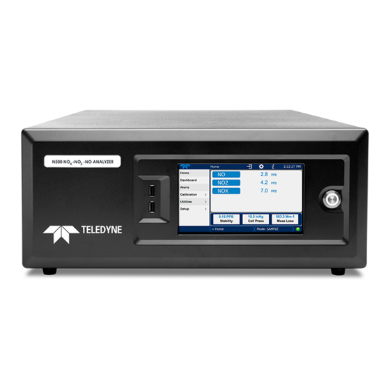
Teledyne N500 CAPS NOx Analyzer Manuals
Manuals and User Guides for Teledyne N500 CAPS NOx Analyzer. We have
1
Teledyne N500 CAPS NOx Analyzer manual available for free PDF download: User Manual
Teledyne N500 User Manual (99 pages)
CAPS NOx Analyzer
Brand:
Teledyne
| Category:
Measuring Instruments
| Size: 9 MB
Table of Contents
Warranty
6
Table of Contents
8
List of Figures
11
1 Introduction, Specifications, Approvals, & Compliance
13
Specifications
13
Table 1-1. Specifications
13
EPA Designation
14
Safety
14
Emc
14
2 Getting Started
15
Unpacking
15
Ventilation Clearance
16
Table 2-1. Ventilation Clearance
16
Instrument Layout
17
Figure 2-1. Front Panel Layout
17
Front Panel
17
Figure 2-2. Rear Panel Layout
18
Rear Panel
18
Table 2-2. Rear Panel Description
18
Figure 2-3. Internal Chassis Layout
19
Internal Chassis
19
Connections and Startup
20
Connecting Power
20
Electrical Connections
20
Connecting Analog Outputs Option
21
Figure 2-4. Analog Outputs Connectors Panel Option
21
Table 2-3. Analog Output Pin Assignments
21
Connecting the Digital I/O Expansion Board Option
22
Figure 2-5. Digital I/O Connector Panel Option
22
Table 2-4. Digital Input/Output Pin Assignments
22
Connecting Communications Interfaces
23
Figure 2-6. JP1 Location and Pin Arrangements
23
Table 2-5. JP1 Configurations for Serial Communication
23
Pneumatic Connections
24
Critical Tubing, Pressure, Venting and Exhaust Requirements
25
Basic Connections from Calibrator
26
Figure 2-7. Gas Line Connections from Calibrator - Basic Configuration
26
Figure 2-8. Pneumatic Flow Diagram Including Zero/Span Valve Option
27
Pneumatic Flow Diagrams
27
Figure 2-9. Pneumatic Flow Diagram Including IZS Valve Option
28
Startup, Functional Checks and Calibration
29
Figure 2-10. Status Screens at Startup
30
Figure 2-11. Home Page Example
30
Startup
30
Alerts: Warnings and Other Messages
31
Figure 2-12. Viewing Active Alerts Page
31
Calibration
32
Figure 2-13. Sample Dashboard Page
32
Functional Checks
32
Menu Overview
33
Table 2-6. Menu Overview
33
Figure 2-14. User Interface Orientation
34
Home Page
34
Figure 2-15. Concentration and Stability Graph (Top) and Meter Graph (Bottom)
35
Dashboard
36
Figure 2-16. Dashboard Page
36
Alerts
37
Figure 2-17. Active Alerts Page
37
Calibration
38
Figure 2-18. Active Alerts Cleared
38
Figure 2-19. Utilities>Alerts Log of Active and Past Alerts and Events
38
Setup
39
Table 2-7. Utilities Submenu Descriptions
39
Utilities
39
Setup Menu: Features/Functions Configuration
40
Figure 2-20. Datalog Configuration, New Log Page
40
Figure 2-21. Datalog Configuration, Existing Log
40
Setup>Data Logging (Data Acquisition System, DAS)
40
Figure 2-22. Creating a New Data Log
41
Configuring Trigger Types: Periodic
42
Figure 2-23. Datalog Periodic Trigger Configuration
42
Configuring Trigger Types: Conditional
43
Downloading das (Data Acquisition System) Data
43
Figure 2-24. Datalog - Conditional Trigger Configuration
43
Figure 2-25. das Download Page
43
Figure 2-26. Events List
44
Setup>Events
44
Figure 2-27. Event Configuration
45
Editing or Deleting Events
46
Figure 2-28. Configured Event Sample
46
Figure 2-29. Edit or Delete an Event
46
Figure 2-30. Dashboard Display and Configuration
47
Setup>Autocal (with Valve Option)
47
Setup>Dashboard
47
Using Events as Triggers for Data Logging
47
Setup>Vars
48
Table 2-8. List of Variables with Descriptions
48
Figure 2-31. Homescreen Configuration
49
Setup>Homescreen
49
Figure 2-32. Digital Outputs Setup
50
Setup>Digital Outputs (Option)
50
Com1
51
Setup>Comm (Communications)
51
Setup>Instrument
51
Table 2-10. COM1 Setup
51
Table 2-9. Setup>Instrument Menu
51
Network Settings
52
TCP Port1
52
TCP Port2
52
Figure 2-33. Communications Configuration, Network Settings
53
Table 2-11. Lan/Ethernet Configuration Properties
53
Transferring Configuration to Other Instruments
54
Figure 2-34. Configuration Transfer
54
3 Communications and Remote Operation
55
Serial Communication
55
Ethernet
55
Table 3-1. Ethernet Status Indicators
55
4 Calibration
56
Important Precalibration Information
56
Calibration Requirements
56
Zero Air
57
Calibration (Span) Gas
57
Span Gas for Multipoint Calibration
57
2 Permeation Tubes
58
Data Recording Devices
58
Calibration Procedures
58
Calibration and Check Procedures for Basic Configuration
59
Figure 4-1. Multi-Point Calibration Page
60
Span Calibration Check and Actual Calibration
60
Zero Calibration Check and Actual Calibration
60
Calibration and Check Procedures with Valve Options Installed
61
Figure 4-2. Zero and Span Calibration Screens
61
Use of Zero/Span Valve with Remote Contact Closure
61
Automatic Zero/Span Cal/Check (Auto Cal)
62
Figure 4-3. Auto Cal Page
62
Table 4-1. AUTO CAL States
63
Table 4-2. Auto Cal Setup Combinations
63
Titration Efficiency (TE) Check/Calibration
64
Table 4-3. Auto Cal Programming Sequence Execution
64
EPA Protocol Calibration
65
5 Maintenance and Service
66
Maintenance Schedule
66
Predictive Diagnostics
67
Table 5-1. Maintenance Schedule
67
Operational Health Checks
68
Figure 5-1: Report Generation Page
68
Table 5-2. Predictive Uses for Dashboard Functions
68
Software/Firmware Updates
69
Remote Updates
69
Manual Reload/Update Procedures
69
Figure 5-2. Remote Update Page
69
Figure 5-3. Manual Update Page (and Other Utilities)
69
Time Zone Changes
71
Figure 5-4. Time Zone Change Requirements
71
Hardware Maintenance Procedures
72
Figure 5-5. Replacing the Sample Filter
72
Replacing the AREF Scrubber and Filter Assembly
72
Replacing the Sample Filter
72
Figure 5-6. Pneumatic Layout of AREF Filter and Charcoal Filter
73
Replacing the Internal Pump
73
Changing the Sample Conditioner
74
Figure 5-7. Internal Pump
74
Checking for Pneumatic Leaks
75
Detailed Pressure Leak Check
75
Performing a Sample Flow Check
76
Service and Troubleshooting
76
Fault Diagnosis with Alerts
77
Table 5-3. Warning Alerts, Fault Conditions and Possible Causes
77
Fault Diagnosis with Dashboard Functions
78
Using the Diagnostic Signal I/O Functions
78
Absence of Analyzer Response to Sample Gas
79
Calibration Problems
79
Negative Concentrations
79
Unstable Zero and Span
79
Inability to Span - Deactivated SPAN Button
80
Inability to Zero - Deactivated ZERO Button
80
Non-Linear Response
80
Excessive Noise
81
Other Performance Problems
81
Slow Response
81
AC Main Power
82
AREF Warnings
82
Subsystem Check for Troubleshooting
82
Lcd/Display Module
83
O 3 Generator Module
83
Internal Span Gas Generator and Valve Options
84
RS-232 Communications
84
Fuse Replacement Procedure
85
Service Procedures
85
Figure 5-8. Fuse Access
86
O 3 Generator Replacement
86
Sample Conditioner Replacement
87
Frequently Asked Questions
88
Technical Assistance
89
6 Principles of Operation
90
Figure 6-1. N500 Optical Absorption Cell
91
Figure 6-2. Phase Shift Representation of Increased Concentration of no
91
Pneumatic Operation
92
Electronic Operation
93
Modules
93
Power Switches
93
Glossary
94
Appendix A - MODBUS Registers
97
Advertisement
Advertisement
Related Products
Teledyne Nano-C2020
Teledyne Nano-C2590
Teledyne Genie Nano-10G Series
Teledyne Genie Nano-5G Series
Teledyne Nano-5G-M2450
Teledyne Nano-5G-M4040
Teledyne Nano-5G-M4500
Teledyne Nano-5G-M5420
Teledyne Nano-5G-M8100
Teledyne Nano-5G-C4060
Teledyne Categories
Measuring Instruments
Analytical Instruments
Test Equipment
Digital Camera
Laboratory Equipment
More Teledyne Manuals
Login
Sign In
OR
Sign in with Facebook
Sign in with Google
Upload manual
Upload from disk
Upload from URL