Sign In
Upload
Manuals
Brands
Tektronix Manuals
Inverter
PG 506
Tektronix PG 506 Manuals
Manuals and User Guides for Tektronix PG 506. We have
2
Tektronix PG 506 manuals available for free PDF download: Instruction Manual
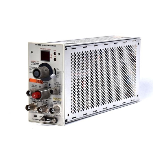
Tektronix PG 506 Instruction Manual (109 pages)
CALIBRATION GENERATOR (SN B040000 AND UP)
Brand:
Tektronix
| Category:
Inverter
| Size: 8 MB
Table of Contents
Table of Contents
4
Electrical Characteristics
10
Specification
10
Environmental Characteristics
12
Physical Characteristics
12
Section 2 Operating Instructions
13
Controls and Connectors
14
Plug-In Installation and Removal
14
Output Load Vs . Voltage out
17
Distortion of Square Waves Caused by Low
21
Warning
22
Contained in Operating Instructions
22
Unless You Are Qualified to Do so
22
Typical Low Frequency Response Curve
21
Section 3 Theory of Operation
24
DVM Timing Diagram for a Negative Input to the Integrator U460
26
Section 4 Calibration Procedure
30
Performance Check
30
Test Equipment Required
30
Attenuator Connections for Current Source
32
100 V Do RANGE DEFLECTION ERROR
33
Do Range DEFLECTION ERROR Resolution Tolerances
33
Resolution Tolerances
33
Standard Amplitude into a 50 O Load
33
Fast Rise and High Amplitude Output Period
35
Typical Response Curve of Sampling System
37
Typical Sampling Oscilloscope Response
38
Typical Sampling Oscilloscope Response Display
38
Adjustment Procedure
40
Adjustment Locations for the A1 Main Circuit Board
41
Adjustment Locations for the A2 DVM/Period Circuit Board
42
Typical Response Curve as Displayed on the Sampling System
45
Typical Response Curve as Displayed on the
45
Selected Component Criteria
46
Corner
48
Pin Assignments for the PG 506 (Rear View, Partial)
48
Relativesusceptibilitytostaticdischarge Damage
50
Display
82
Calibration Generator
106
Advertisement
Tektronix PG 506 Instruction Manual (99 pages)
CALIBRATION GENERATOR
Brand:
Tektronix
| Category:
Inverter
| Size: 47 MB
Table of Contents
Table of Contents
3
PG 506 Calibration Generator
8
Electrical Characteristics
9
Secti on 1 Specification
9
Environmental Characteristics
11
Physical Characteristics
11
Operating Instructions
13
Controls and Connectors
14
Plug-In Installation and Removal
14
Output Load Vs
17
Distortion of Square Waves Caused by Low
21
Typical Waveform Showing Ringing at Front Corner
21
Warning
23
The Following Service Instructions Are
23
For Use by Qualified Personnel Only. to
23
Avoid Personal Injury, Do Not Perform
23
Section 3 Theory of Operation
25
3-1. DVM Timing Diagram for a Negative Input to the Integrator U460
28
Calibration Procedure
31
Performance Check
31
Test Equipment Required
31
Standard Amplitude (into 1 MO) Within 0.25%, ±1 Jn
33
DC Range DEFLECTION ERROR Resolution Tolerances
35
Standard Amplitude into a 50 0 Load
35
Fast Rise and High Amplitude Output Period
37
Typical Sampling Oscilloscope Response
40
Adjustment Procedure
42
Adjustment Locations for the A2 DVM/Period Circuit Board
44
Adjustment Locations for the A3 Fast Rise
46
Typical Response Curve as Displayed on the Sampling System
47
Selected Component Criteria
49
Circuit Board
50
Pin Assignments for the PG 506 (Rear View, Partial)
51
Main Interface Board (Partial) Showing Amplitude and Trigger Output Cable Connections
52
Relative Susceptibility to Static Discharge Damage
53
Replaceable Electrical Parts
57
Replaceable Mechanical Parts
90
Advertisement
Related Products
Tektronix PPG3000 Series
Tektronix PPG3002
Tektronix PPG3004
Tektronix PPG3200 Series
Tektronix PED3200 Series
Tektronix PPG3201
Tektronix PPG3204
Tektronix PED3201
Tektronix PED3202
Tektronix PFG 5105
Tektronix Categories
Test Equipment
Measuring Instruments
Amplifier
Portable Generator
Printer
More Tektronix Manuals
Login
Sign In
OR
Sign in with Facebook
Sign in with Google
Upload manual
Upload from disk
Upload from URL