Sign In
Upload
Manuals
Brands
Tektronix Manuals
Measuring Instruments
PA3000
Tektronix PA3000 Manuals
Manuals and User Guides for Tektronix PA3000. We have
2
Tektronix PA3000 manuals available for free PDF download: User Manual, Installation & Safety Manual
Tektronix PA3000 User Manual (178 pages)
Power Analyzer
Brand:
Tektronix
| Category:
Measuring Instruments
| Size: 9 MB
Table of Contents
Table of Contents
7
Important Safety Information
13
General Safety Summary
13
Service Safety Summary
16
Terms in this Manual
17
Symbols and Terms on the Product
17
Compliance Information
18
EMC Compliance
18
Safety Compliance
19
Environmental Considerations
21
Preface
23
Features and Abilities
23
Figure I: Tektronix PA3000 Power Analyzer
23
Getting Started
25
Before You Begin - Safety
25
Power on
26
Concept of Global, Group, and Channel Parameters
27
Connecting to the Product under Test
28
Figure 1: Typical PA3000 Input Connections
28
Figure 2: Rear Panel Input Module
29
Results Screen
30
Figure 3: Result Screen (Four-Channel Instrument)
30
Navigating the Results Screen
31
Figure 4: Left and Right Arrow Hard Keys
31
Navigating the Menu System
32
On-Screen Help
33
Front Panel
35
Front Panel Controls and Connectors
35
Figure 5: Front Panel Controls and Connectors
35
Table 1: Front Panel Controls and Connectors
35
Quick View Keys
36
Figure 6: Quick View Keys
36
Results Screen
37
Figure 7: Results Screen
37
Waveform Screen
38
Figure 8: Waveform Screen
38
Bar Chart Screen
39
Figure 9: Bar Chart Screen
39
Integrator Screen
41
Figure 10: Integrator Screen
41
Vector Screen
43
Figure 11: Vector Screen
43
Math Screen
44
Figure 12: Math Screen
44
Setup Screen
45
Figure 13: Setup Screen (First Screen)
45
Front Panel USB Port
46
Figure 14: Setup Screen (Second Screen)
46
Soft Keys
47
Menu and Help Keys
48
Operational and Alphabetical Keys
48
Figure 15: Operational and Alphabet Keys
48
Number and Formula Keys
49
Logging Data to a Storage Device
50
Figure 16: Example Data File
51
Connecting Signals
52
Input Overview
52
Figure 17: Signal Inputs on Rear Panel (Channel 1 Shown)
52
Table 2: Signal Inputs on Rear Panel
52
To Connect a Simple Current Transformer
54
Figure 18: Current Transformer Connections
54
To Connect an External Resistive Shunt
55
Figure 19: External Resistive Shunt Connections
55
To Connect a Transducer with a Voltage Output
57
To Connect a Voltage Transformer / Transducer
58
Figure 20: Current Transformer Connections
58
Power for External Transducers
59
Figure 21: External Resistive Shunt Connections
59
The Menu System
60
Measurements
60
Figure 22: Measurements Screen
60
Measurement Configuration Menu
62
Figure 23: Example of a Moved Measurement
62
Figure 24: Measurement Configuration Menu
62
Table 3: Weighing Factors for TIF
65
Modes
66
Table 4: Effects of Frequency Range Settings in PWM Mode
70
Inputs
71
Figure 25: Single-Phase, Two-Wire and DC Measurements. Select 1 Phase, 2 Wire Mode
71
Figure 26: Single-Phase, Three-Wire. Select 1 Phase, 3 Wire
72
Figure 27: Three-Phase, Three-Wire (2 Wattmeter Method). Select 3 Phase, 3 Wire
72
Figure 28: Three Phase, Three Wire (3 Wattmeter Method). Select 3 Phase, 3 Wire (3V3A)
72
Figure 29: Three-Phase, Three-Wire (3 Wattmeter Method). Select 3 Phase, 4 Wire
73
Figure 30: Three-Phase, Four-Wire (3 Wattmeter Method). Select 3 Phase, 4 Wire
73
Table 5: Input Ranges
74
Graphs and Waveforms
77
Interfaces
78
Datalog
80
Math Results
80
Table 6: Valid Channel Parameters
81
Table 7: Valid Group Parameters
82
Table 8: Valid Group Sum Parameters
82
Table 9: Parameters for Returning Values from the Analog and Counter Inputs
82
System Configuration
83
User Configuration
85
Remote Operation
86
Overview
86
Interfacing with RS-232 Systems
86
Interfacing with USB Systems
86
Interfacing with Ethernet Systems
86
Interfacing with GPIB Systems (Optional)
87
Status Reporting
87
Figure 31: Status Byte
87
Figure 32: Status Byte Register
88
Figure 33: Display Data Status Register
88
Figure 34: Display Data Status Enable Register
88
Table 10: Status Byte Register Bit Definitions
88
Table 11: Display Data Status Register Bit Definitions
88
Table 12: Display Data Status Enable Register Bit Definitions
88
Figure 35: Standard Event Status Register
89
Figure 36: Standard Event Status Enable Register
89
Table 13: Standard Event Status Register Bit Definitions
89
Table 14: Standard Event Status Enable Register Bit Definitions
89
Command Listing
90
IEEE 488.2 Standard Commands and Status Commands
91
Channel and Group Commands
93
Unit Information Commands
94
Measurement Selection and Reading Commands
94
Measurement Configuration Commands
98
Mode Setup Commands
103
Input Setup Commands
107
Graph and Waveform Commands
112
Interface Commands
113
Datalog Commands
114
Screen Save Commands
115
Math Commands
115
System Configuration Commands
116
User Configuration Commands
119
Sending and Receiving Commands
120
Communications Examples
121
PA3000 Software
124
PWRVIEW PC Software
124
Figure 37: PWRVIEW Software
124
Firmware Update Utility
125
Application Examples
127
Example 1: Efficiency Testing Single Phase Applications
128
Figure 38: AC-DC Efficiency Measurement Wiring Diagram
129
Figure 40: Harmonic Bar Chart on the PA3000
132
Figure 42: Efficiency Trend Chart
134
Figure 43: Logging Setup
135
Example 2: Efficiency Testing Three Phase Applications
136
Figure 45: PWM Motor Drive Efficiency (1 Phase in and 3 Phase Out)
138
Figure 46: Vector Graph on the PA3000
140
Figure 47: PWM Motor Drive Efficiency (3 Phase in and 3 Phase Out)
141
Figure 48: Auxiliary Inputs Setup for Torque and Speed Measurements
143
Figure 49: Harmonic Bar Chart
144
Example 3: Energy Consumption Testing
145
Figure 50: Energy Consumption Measurements Wiring Diagram
146
Figure 51: Energy Consumption Testing on the PA3000
147
Figure 52: Integration Trend Chart
150
Example 4: Standby Power Measurements (IEC 62301 Ed. 2.0)
151
Figure 54: Standby Power Measurements Wiring Diagram
152
Figure 55: Standby Power Mode
153
Figure 56: Full Compliance IEC 62301 Standby Power Test
154
Figure 57: IEC 62301 Ed. 2.0 Standby Power Test Report
156
Example 5: Inrush Current Testing
157
Figure 58: Inrush Current Measurement Wiring Diagram
158
Figure 59: Min-Max Columns for the Inrush Current Measurement
159
Figure 60: Inrush Current Measurement
160
Reference Information
163
Measured Parameters
163
Table 15: Phase Measurements
163
Accuracy Equations
165
Table 16: Measurement Accuracy
165
Sum Equations
166
Table 17: One Phase, Three Wire Sum Equations
166
Table 18: Three Phase, Three Wire Sum Equations
167
Table 19: Three Phase, Four Wire Sum Equations
168
Communication Ports
170
Table 20: USB Connector Pin Descriptions
170
Table 21: Communication Ports on the Rear Panel
171
Figure 61: Power Analyzer Communication Ports on the Rear Panel
171
Table 22: Ethernet Pin Descriptions
172
Table 23: GPIB Port Pin Configuration Descriptions
172
Table 24: Auxiliary Input-Output Pin Descriptions
173
Table 25: RS-232 Connector Pin Descriptions
173
Advertisement
Tektronix PA3000 Installation & Safety Manual (38 pages)
Power Analyzer
Brand:
Tektronix
| Category:
Measuring Instruments
| Size: 3 MB
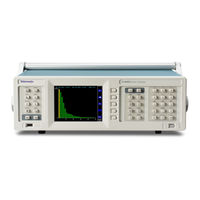
Table of Contents
Watch Video
3
Test Setup
3
Watch Video
19
Contact Information
38
Advertisement
Related Products
Tektronix PA4000 Series
Tektronix PA1000
Tektronix P6106A
Tektronix PSM5120
Tektronix P7350
Tektronix P6202A
Tektronix P6900 Series
Tektronix P6135A
Tektronix PRIMER P5100
Tektronix P6025
Tektronix Categories
Test Equipment
Measuring Instruments
Amplifier
Portable Generator
Printer
More Tektronix Manuals
Login
Sign In
OR
Sign in with Facebook
Sign in with Google
Upload manual
Upload from disk
Upload from URL