Sign In
Upload
Manuals
Brands
Tektronix Manuals
Measuring Instruments
P6900 Series
Tektronix P6900 Series Logic Analyzer Manuals
Manuals and User Guides for Tektronix P6900 Series Logic Analyzer. We have
1
Tektronix P6900 Series Logic Analyzer manual available for free PDF download: Instruction Manual
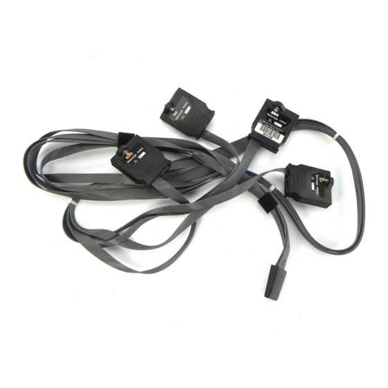
Tektronix P6900 Series Instruction Manual (82 pages)
High-Density Logic Analyzer Probes with D-Max Probing Technology
Brand:
Tektronix
| Category:
Measuring Instruments
| Size: 1 MB
Table of Contents
Table of Contents
5
Preface
9
Related Documentation
9
Environmental Considerations
10
Commonly Used Terms
10
Figure I: Differential Input Amplitude
11
Figure II: Flying Lead Set
11
Figure III: Probe Example
12
Operating Basics
13
Product Description
13
Figure 1: P6960 High-Density Probe with D-Max Probing Technology
14
Figure 2: P6960HS High-Density Probe with D-Max Probing Technology
15
Figure 3: P6962 High-Density Probe with D-Max Probing Technology
16
Figure 4: P6964 High-Density Probe with D-Max Probing Technology
18
Figure 5: P6980 High-Density Differential Probe with D-Max Probing Technology
19
Figure 6: P6982 High-Density Differential Probe with D-Max Probing Technology
20
Connect the Probes to the Logic Analyzer
22
Figure 7: Connecting the Probes to the Logic Analyzer
22
Connect the Probes to the Target System
23
Figure 8: Replacing the Wires on the Retention Posts
23
Figure 9: Installing the Retention Posts in the PCB
24
Figure 10: Soldering the Retention Posts in the PCB
25
Figure 11: Installing the Alternate Retention Assembly
26
Figure 12: Proper Handling of the Interface Clip
27
Figure 13: Connecting the Probes to the Target System
28
Figure 14: Using the Flying Lead Set to Connect to the Target System
30
Dress the Probe Cables
31
Figure 15: Proper Dressing of the Probe Cables
31
Store the Probe Heads
32
Figure 16: Protecting the Probe Heads
32
Reference
33
Probe and Target System Interface Design Information
33
Table 1: Logic Analyzer Clock and Qualifier Availability
34
Table 2: 2X Demultiplexing Source-To-Destination Channel Assignments
36
Table 3: 4X Demultiplexing Source-To-Destination Channel Assignments
37
Board Design
39
Figure 17: P6960, P6960HS, P6980, and P6982 Probe Dimensions
39
Figure 18: P6962 and P6964 Probe Dimensions
40
Figure 19: Retention Post Dimensions
41
Figure 20: Keepout Area
41
Figure 21: Side-By-Side Layout
42
Figure 22: End-To-End Layout
42
Figure 23: Alternate Retention Assembly Dimensions
42
Figure 24: Keepout Area
43
Figure 25: Side-By-Side Layout
43
Figure 26: End-To-End Layout
44
Figure 27: Signal Routing on the Target System
44
Figure 28: High-Density Probe Load Model
46
Probe Footprint Dimensions
47
Figure 29: Probe Footprint Dimensions on the PCB
47
Other Design Considerations
48
Figure 30: Optional Via-In-Pad Placement Recommendation
48
Probe Pinout Definition and Channel Assignment
49
Figure 31: P6960/P6960HS Single-Ended PCB Footprint Pinout Detail
49
Table 4: Channel Assignment for P6960/P6960HS Single-Ended Data, Differential Clock Logic Analyzer
49
Figure 32: P6962 Single-Ended PCB Footprint Pinout Detail
51
Table 5: Channel Assignment for a P6962 Single-Ended Data, Differential Clock Logic Analyzer Probe
52
Figure 33: P6964 Single-Ended PCB Footprint Pinout Detail
53
Table 6: Channel Assignment for a P6964 Single-Ended Data, Differential Clock Logic Analyzer Probe
54
Figure 34: P6980 Differential PCB Footprint Pinout Detail
56
Table 7: Channel Assignment for a P6980 Differential Clock and Data Logic Analyzer Probe to a 136- or 102-Channel Logic Analyzer Module
56
Table 8: Channel Assignment for a P6980 Differential Clock and Data Logic Analyzer Probe to a 68- or 34-Channel Logic Analyzer Module
58
Figure 35: P6982 Differential PCB Footprint Pinout Detail
60
Table 9: Channel Assignment for a P6982 Differential Clock and Data Logic Analyzer Probe to a 136- or 102-Channel Logic Analyzer Module
60
Table 10: Channel Assignment for a P6982 Differential Clock and Data Logic Analyzer Probe to a 68- or 34-Channel Logic Analyzer Module
62
Specifications
65
Mechanical and Electrical Specifications
65
Table 11: Mechanical and Electrical Specifications
65
Table 12: Environmental Specifications
66
Maintenance
67
Probe Calibration
67
Perform the Functional Check
67
Inspect and Clean the Probes
67
Service Strategy
68
Legacy Probe and Attachment Support
68
Repackaging Instructions
69
Replaceable Parts
71
Parts Ordering Information
71
Replaceable Parts List
72
Table 13: Parts List Column Descriptions
72
Table 14: P6960 Replaceable Parts List
73
Table 15: P6960HS Replaceable Parts List
74
Table 16: P6962 Replaceable Parts List
75
Table 17: P6964 Replaceable Parts List
76
Table 18: P6980 Replaceable Parts List
77
Table 19: P6982 Replaceable Parts List
78
Table 20: P6900 Series Probes Optional Accessories
79
Index
81
Advertisement
Advertisement
Related Products
Tektronix P6910
Tektronix P6562A
Tektronix P6112
Tektronix P6330
Tektronix P6204
Tektronix P6207
Tektronix P6135A
Tektronix P6201
Tektronix P6202
Tektronix P6009
Tektronix Categories
Test Equipment
Measuring Instruments
Amplifier
Portable Generator
Printer
More Tektronix Manuals
Login
Sign In
OR
Sign in with Facebook
Sign in with Google
Upload manual
Upload from disk
Upload from URL